
Elevator cabin with integrated ventilation system

Inactive Publication Date: 2005-06-09
INVENTIO AG
View PDF4 Cites 9 Cited by
  • Summary
  • Abstract
  • Description
  • Claims
  • Application Information

AI Technical Summary

Benefits of technology

[0008] Accordingly, it is an object of the present invention to provide an elevator cabin with a ventilation system without the drawbacks mentioned above. The new elevator cabin should be protected against noise from the operating apparatus of the elevator system and should comprise an efficient ventilation system, without increasing costs of the cabin.
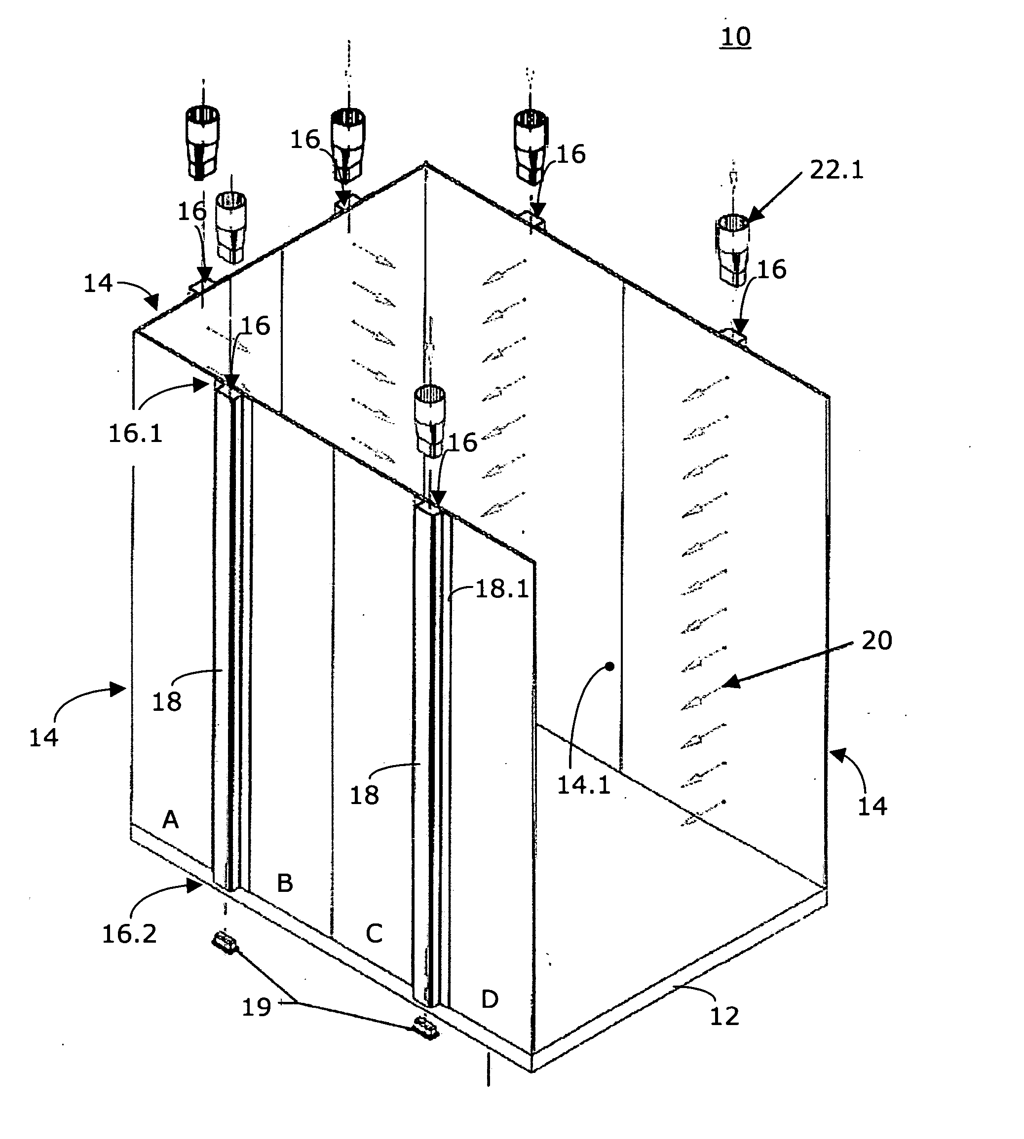
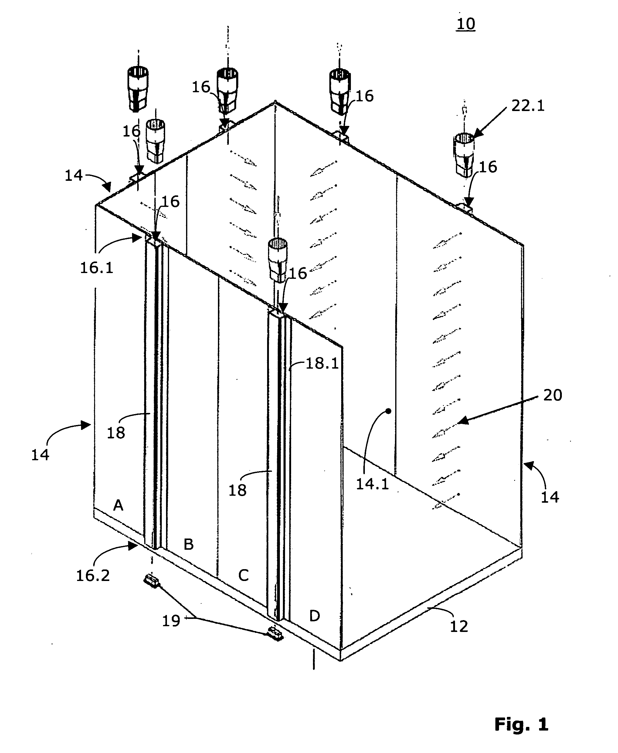
[0011] The comfort of the passengers is improved, due to the new system of air distribution. Not only is noise greatly reduced, but the air is distributed uniformly in the entire elevator cabin. Any draft is prevented and air is not fed from the ceiling but instead from the side.
[0012] Optionally, the ventilation holes can be arranged so that the air is not fed at 90° from the side walls, hereby a circulating effect can be created, either in horizontal direction or slightly inclined.
[0013] The esthetic aspect of the interior of the elevator cabin is improved, due to the reduced dimensions of the ventilation holes. The distribution of the ventilation holes can even be used to achieve decorative effects. It is also possible to distribute the ventilation holes in the form of letters to provide information for the passengers.
[0014] The costs of the ventilation system are low. Although the air is fed to the elevator cabin through a plurality of ventilation holes, the system works with a single fan.
[0015] The side walls or panels of the elevator cabin are reinforced due to the integrated air channels. Due to this reinforcing effect, lighter side walls, respectively panels, can be used. This too reduces the costs not only of the constructive elements of the elevator but also the operating costs.

Problems solved by technology

It is a drawback of certain ventilation systems that noise from the operating apparatus of the elevator enters into the elevator cabin through the different ventilation openings.
One drawback is that the elevator cabin is not protected against noise entering from the ceiling.
But if a drop ceiling is employed in the cabin, it is not as easy to obtain a satisfactory ventilation of the elevator cabin, since the drop ceiling restricts the air flow.
Another drawback of this elevator cabin is that the venting is effected by air being fed to the elevator cabin through one inlet only.
Also, the air will not be distributed evenly in the elevator cabin.
Further, the direction of the ventilating air from the ceiling to the floor usually is not comfortable for the passengers.

Method used


Image

  • Elevator cabin with integrated ventilation system
  • Elevator cabin with integrated ventilation system
  • Elevator cabin with integrated ventilation system

Examples


Embodiment Construction

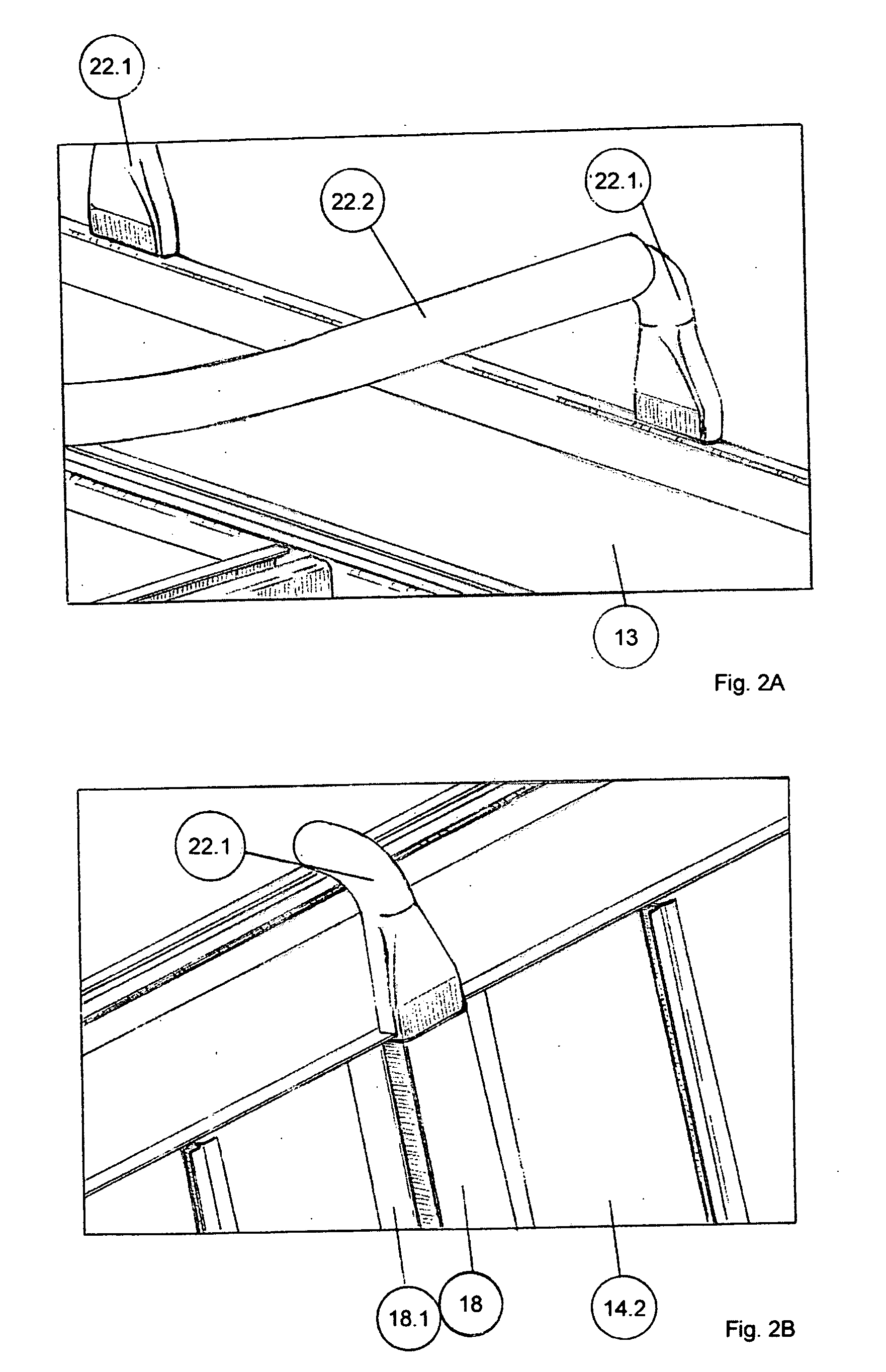
[0023]FIG. 1 shows the inner part of an elevator cabin 10 in accordance with the present invention. The inner part of elevator cabin 10 comprises a floor 12, a ceiling or roof 13, shown only in FIG. 2A, and side walls 14. The side walls 14 have inner surfaces 14.1 facing the inner room of the elevator cabin 10 and outer surfaces 14.2 facing the mechanical structure of the elevator cabin or the shaft in which the elevator cabin can move up- and down-wards. Neither the mechanical structure of the elevator cabin nor the elevator shaft are shown in FIG. 1.

[0024] Vertical air or ventilation channels 16 are disposed along the side walls 14 of the elevator cabin 10. In the embodiment represented in FIG. 1, each of the side walls 14 has two air channels 16.

[0025] In other embodiments, not shown, the air channels are not disposed entirely in vertical direction, and each side wall of the elevator cabin may have more or less than two air channels, or a part of the side walls of the elevator ...


PUM


Abstract

An elevator cabin with an integrated ventilation system. A fan is attached to the elevator cabin and a vertical side wall of the elevator cabin has a plurality of distributed ventilation holes. At least one air channel element is attached to the side wall, so that the air channel element together with the adjacent portion of the side wall forms an air channel. An adapter element is situated between the fan and an inlet opening of the air channel for guiding air from the fan into the air channel so that the air travels from the fan through the adapter element into the air channel and through the ventilation holes into the elevator cabin.

Description

The present invention relates to an elevator cabin having an integrated ventilation system. BACKGROUND OF THE INVENTION [0001] Some elevator cabins simply have air inlet and outlet openings in the lower and upper portion of the elevator cabin body. These inlets and outlets are in direct connection with the outside air. [0002] Many elevator cabins nowadays comprise a motor driven fan mounted on the roof of the cabin. The motor drives a fan blade to draw air from the elevator shaft into the elevator cabin and from there back into the elevator shaft. Conventional cabins have a simple fan opening in the ceiling which serves as an air inlet and sometimes simple ventilation openings in the side walls. The air inlet may be covered by an air duct. [0003] It is a drawback of certain ventilation systems that noise from the operating apparatus of the elevator enters into the elevator cabin through the different ventilation openings. [0004] JP-2001 294 384 discloses an elevator cabin which is f...

Claims


Application Information

Patent Timeline
IPC IPC(8): B66B11/00B66B11/02F24F7/00
CPCB66B11/024
Inventor SANTOS, AGNALDO
Owner INVENTIO AG
Learn More