
Connecting rod and manufacturing method thereof

Active Publication Date: 2018-03-29
HONDA MOTOR CO LTD
View PDF0 Cites 5 Cited by
  • Summary
  • Abstract
  • Description
  • Claims
  • Application Information

AI Technical Summary

Benefits of technology

[0026]As discussed above, the present invention provides a connecting rod which can be manufactured without increasing the cost, and is provided with an effectively strengthened rod portion, and a manufacturing method thereof.

Problems solved by technology

Therefore, the forging equipment becomes large in size and the manufacturing cost increases.
In the case of the method described in Patent Document 2 also, a large forging load is required to increase the strength of the entire rod portion, and the die structure becomes complicated.
Therefore, the manufacturing cost increases.
Further, in the case of the method of manufacturing a connecting rod described in Patent Document 3, because only the tip end portions of each rib are work hardened, and the hardness of the root portion of the rib is limited, a sufficient buckling strength for the rod portion cannot be obtained.

Method used


Image

  • Connecting rod and manufacturing method thereof
  • Connecting rod and manufacturing method thereof
  • Connecting rod and manufacturing method thereof

Examples


Embodiment Construction

)

[0032]An embodiment of the present invention is described in the following with reference to appended drawings.

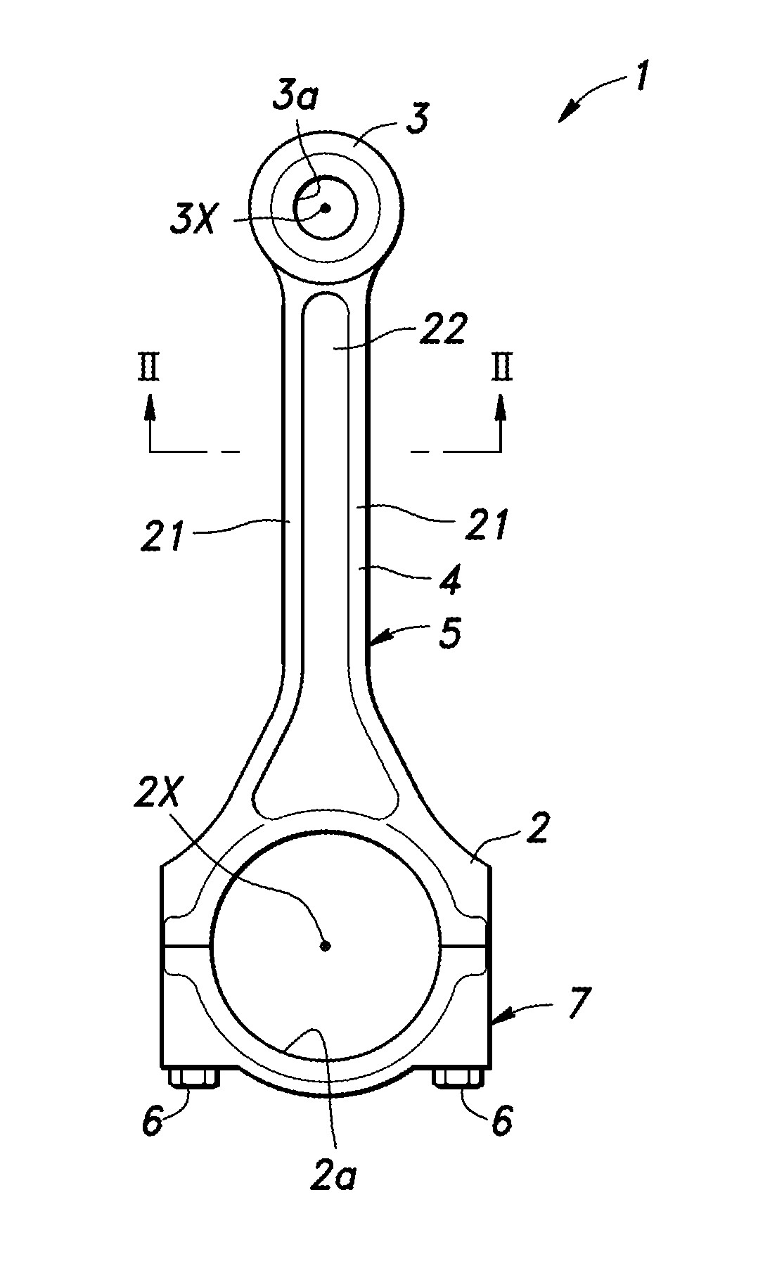
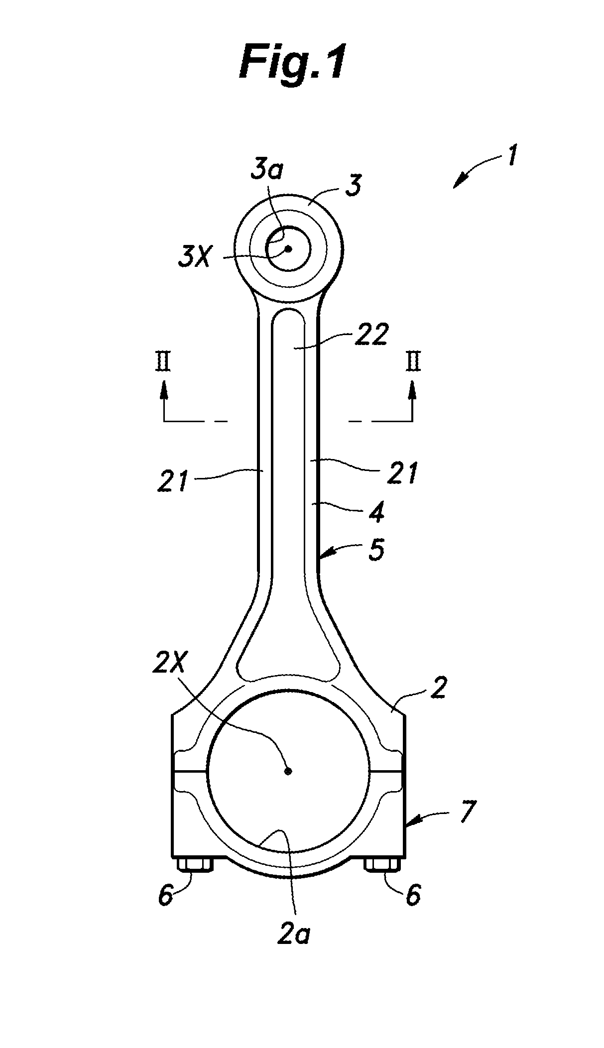
[0033]As shown in FIG. 1, the connecting rod 1 includes a big end 2 coupled to a crankshaft (not shown in the drawing), a small end 3 coupled to a piston (not shown in the drawing), and a rod portion 4 connected between the big end 2 and the small end 3. The big end 2 forms an annular bearing surrounding a crank pin of the crankshaft, and defines a crank pin bore 2a having a circular cross section. The small end 3 forms an annular bearing surrounding a piston pin, and defines a piston pin bore 3a having a circular cross section. The big end 2 and the small end 3 are provided with axial lines 2X and 3X, respectively, which are parallel to each other. The connecting rod 1 includes a connecting rod main body 5 formed by the small end 3, the rod portion 4 and a half of the big end 2, and a cap 7 which is fastened to the half of the big end 2 on the side of the connecting rod m...


PUM


Abstract

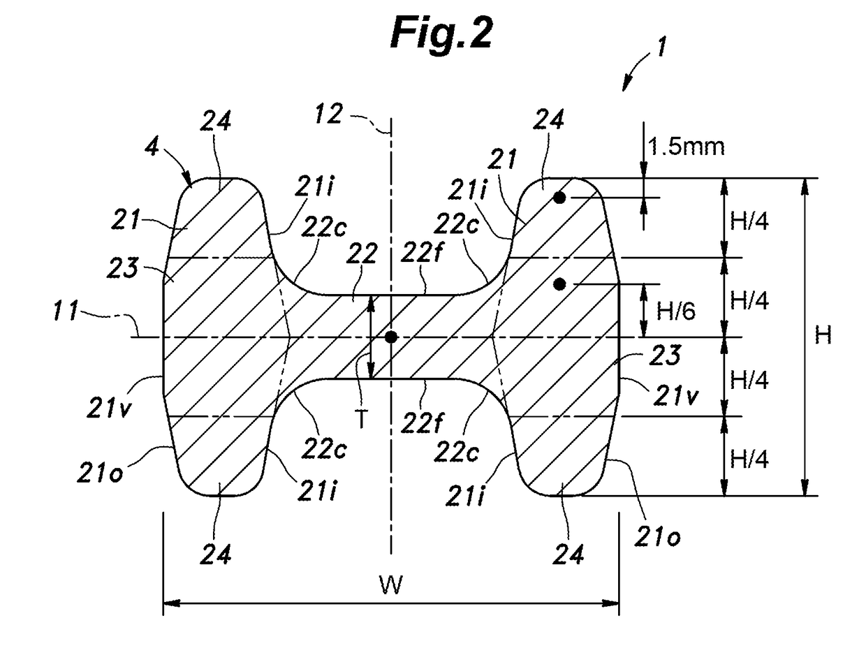
Provided is a connecting rod which can be manufactured without increasing the cost, and is provided with an effectively strengthened rod portion. The rod portion includes a pair of ribs (21) extending in parallel to each other in cross sectional view, and a web (22) connected between substantially vertically middle parts of the ribs. Each rib includes a rib root portion (23) located in a vertically central part thereof in cross sectional view, and a pair of rib tip portions (24) located at both vertical ends thereof, and each rib tip portion has a higher hardness than the web by 40 HV or more, and the rib root portion has a higher hardness than the web by 30 HV or more.

Description

TECHNICAL FIELD[0001]The present invention relates to a connecting rod connecting a piston with a crankshaft in an internal combustion engine, and in particular, to a connecting rod including a locally strengthened rod portion connecting a big end with a small end, and a manufacturing method thereof.BACKGROUND ART[0002]As a manufacturing method for effectively increasing the strength of the rod portion of a connecting rod, it is known to perform a hot forging step for hot forging the rod portion including a web consisting of a plate strip and two ribs projecting from either side edge of the web (so as to have an H-shaped cross section), a cold forging step using an open die assembly exposing both side edges of the web while enclosing the remaining part of the web and the ribs for cold forging the rod portion while allowing burr to protrude from either open side end of the open die assembly until the cross sectional area of the rod portion is reduced by 10 to 30%, and a step for remo...

Claims


Application Information

Patent Timeline
IPC IPC(8): F16C7/02B21D53/84B21D37/16F16C9/04
CPCF16C7/023B21D53/84B21D37/16F16C9/045F16J1/16F16C2360/22
Inventor MATSUDA, HIDEKIIWASAKI, YASUYUKIHAYASHI, HIROSHI
Owner HONDA MOTOR CO LTD
Learn More