Method for producing chiral metal oxide structure, and chiral porous structure
- Summary
- Abstract
- Description
- Claims
- Application Information
AI Technical Summary
Benefits of technology
Problems solved by technology
Method used
Image

Examples
example 1
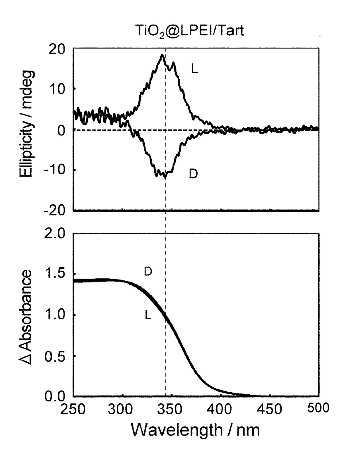
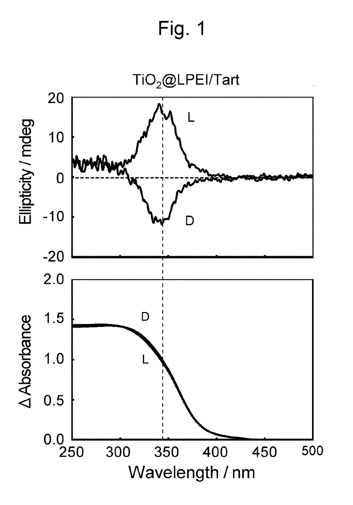
[0069]158 mg (equivalent to 2 mmol of the secondary amino groups) of powdered LPEI (water content: 46 mass %) was added to distilled water (40 mL) and the mixture was heated to about 100° C. to prepare a polymer solution containing completely dissolved LPEI. Separately, 150 mg (1 mmol) of powdered D-tartaric acid (Tokyo Chemical Industry Co., Ltd.) was dissolved in distilled water (40 mL) at about 100° C. to prepare a dicarboxylic acid solution. Then, the carboxylic acid solution was poured into the polymer solution maintained at about 100° C. to prepare an aqueous mixture. The aqueous mixture was spontaneously cooled to room temperature and then was left to stand at 4° C. overnight. The next day, the composite of the polymer and the D-tartaric acid (chiral supramolecular crystal), which was generated in the aqueous mixture, was washed with a centrifuge. A mixture of titanium lactate (manufactured by Matsumoto Fine Chemical Co., Ltd., Orgatix TC-310 (titanium lactate 44 mass % aqueo...
example 2
[0074]A composite of LPEI, L-tartaric acid, and titanium oxide (TiO2@LPEI / L-Tart) and a titanium oxide structure (TiO2@L) were prepared as in Example 1 except that L-tartaric acid (Tokyo Chemical Industry Co., Ltd.) was used instead of D-tartaric acid. The yield of the composite of LPEI, L-tartaric acid, and titanium oxide was 537 mg. The reduced mass (%) of the composite after calcination is shown in Table 1.
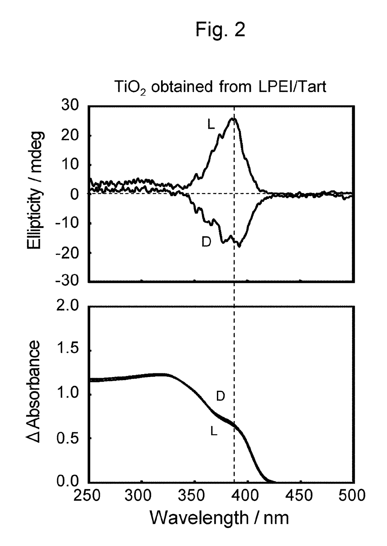
[0075]Diffuse-reflection circular dichroism spectra were obtained of the composite of LPEI, L-tartaric acid, and titanium oxide (TiO2@LPEI / L-Tart) and the titanium oxide structure prepared by calcination at 600° C. (TiO2@L), each of which had been pulverized in a mortar and dispersed in KCl at a concentration of 40 mass % before measurement. FIG. 1 (Reference sign (L)) and FIG. 2 (Reference sign (L)), respectively, illustrate the spectra of the composite of LPEI, L-tartaric acid, and titanium oxide (TiO2@LPEI / L-Tart) and the titanium oxide structures which resulted from calcina...
reference example 1
[Reference example 1]
[0078]A composite of LPEI and DL-tartaric acid (TiO2@LPEI / DL-Tart), and a titanium oxide structure (TiO2@DL), were prepared as in Example 1 except that DL-tartaric acid (Tokyo Chemical Industry Co., Ltd.) was used instead of D-tartaric acid. The reduced mass (%) of the composite after calcination is shown in Table 1.
[0079]Diffuse-reflection circular dichroism spectra were measured for the composite of LPEI, DL-tartaric acid, and titanium oxide (TiO2@LPEI / DL-Tart) and for the titanium oxide structure prepared by calcination at 600° C. (TiO2@DL), each of which had been pulverized in a mortar and dispersed in KCl at a concentration of 40 mass % before the measurement. FIG. 9 and FIG. 10, respectively, illustrate the spectra of the composite of LPEI, DL-tartaric acid, and titanium oxide (TiO2@LPEI / DL-Tart) and the titanium oxide structures formed through calcination at 600° C. (TiO2@DL).
[0080]XRD was carried out for each of the titanium oxide structures (TiO2@DL) ca...
PUM
| Property | Measurement | Unit |
|---|---|---|
| Particle size | aaaaa | aaaaa |
| Fraction | aaaaa | aaaaa |
| Fraction | aaaaa | aaaaa |
Abstract
Description
Claims
Application Information
 - R&D
- Intellectual Property
- Life Sciences
- Materials
- Tech Scout
- Unparalleled Data Quality
- Higher Quality Content
- 60% Fewer Hallucinations
Browse by: Latest US Patents, China's latest patents, Technical Efficacy Thesaurus, Application Domain, Technology Topic, Popular Technical Reports.
© 2025 PatSnap. All rights reserved.Legal|Privacy policy|Modern Slavery Act Transparency Statement|Sitemap|About US| Contact US: help@patsnap.com