
A sensor device for a braking system equipped with an electromechanical brake booster and a method for ascertaining a braking request specification to a braking system equipped with an electromechanical brake booster

a technology of electromechanical brake and sensor device, which is applied in the direction of braking system, vehicle sub-unit features, transportation and packaging, etc., can solve the problems of limited suitability, increased pedal travel, and often no longer possible pedal travel

Inactive Publication Date: 2017-09-21
ROBERT BOSCH GMBH
View PDF3 Cites 5 Cited by
  • Summary
  • Abstract
  • Description
  • Claims
  • Application Information

AI Technical Summary

Benefits of technology

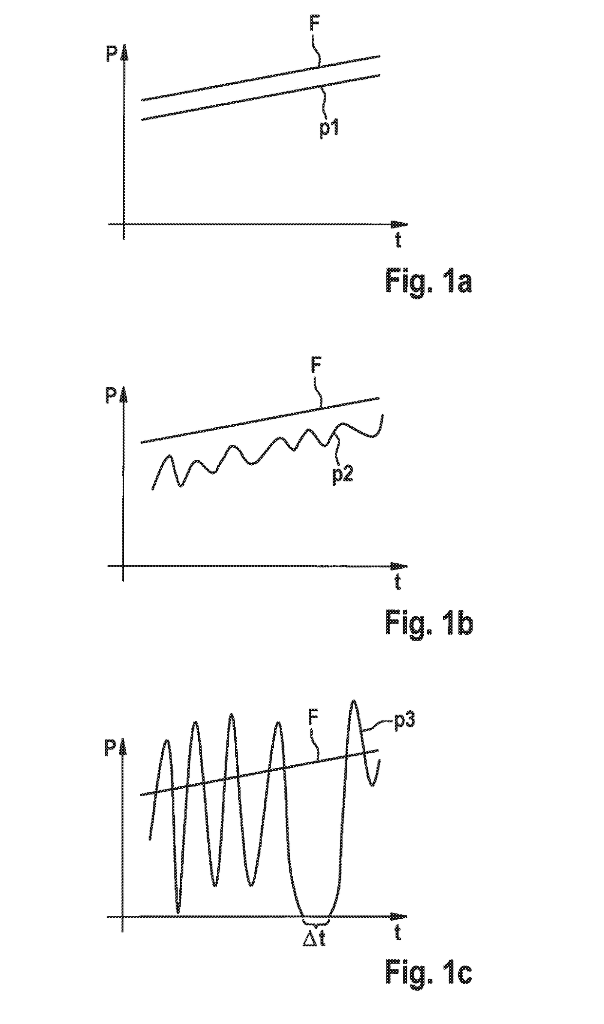
The present invention provides a way to determine the braking request of a user of a braking system with an electromechanical brake booster. This is done by using the fact that the electromechanical brake booster and the driver's braking request have the same dynamic. This is different from using hydraulic variables, which have a significantly lower time constant. The evaluation electronics can determine the braking request by taking into account various actual or setpoint variables, such as motor current, voltage, power, rotation angle, speed, adjustment travel, force, etc. This allows for accurate and error-free determination of the braking request, which can be used for various braking functions. The braking system with an electromechanical brake booster and the corresponding sensor device / controller provide the advantages of the invention.

Problems solved by technology

In contrast, an increase in the pedal travel is frequently no longer possible after the closing of at least one of the valves of the hydraulics such as, for example, a brake circuit separating valve, which is why the pedal travel in this case is of only limited suitability for reproducing a braking request.

Method used


Image

  • A sensor device for a braking system equipped with an electromechanical brake booster and a method for ascertaining a braking request specification to a braking system equipped with an electromechanical brake booster
  • A sensor device for a braking system equipped with an electromechanical brake booster and a method for ascertaining a braking request specification to a braking system equipped with an electromechanical brake booster
  • A sensor device for a braking system equipped with an electromechanical brake booster and a method for ascertaining a braking request specification to a braking system equipped with an electromechanical brake booster

Examples


Embodiment Construction

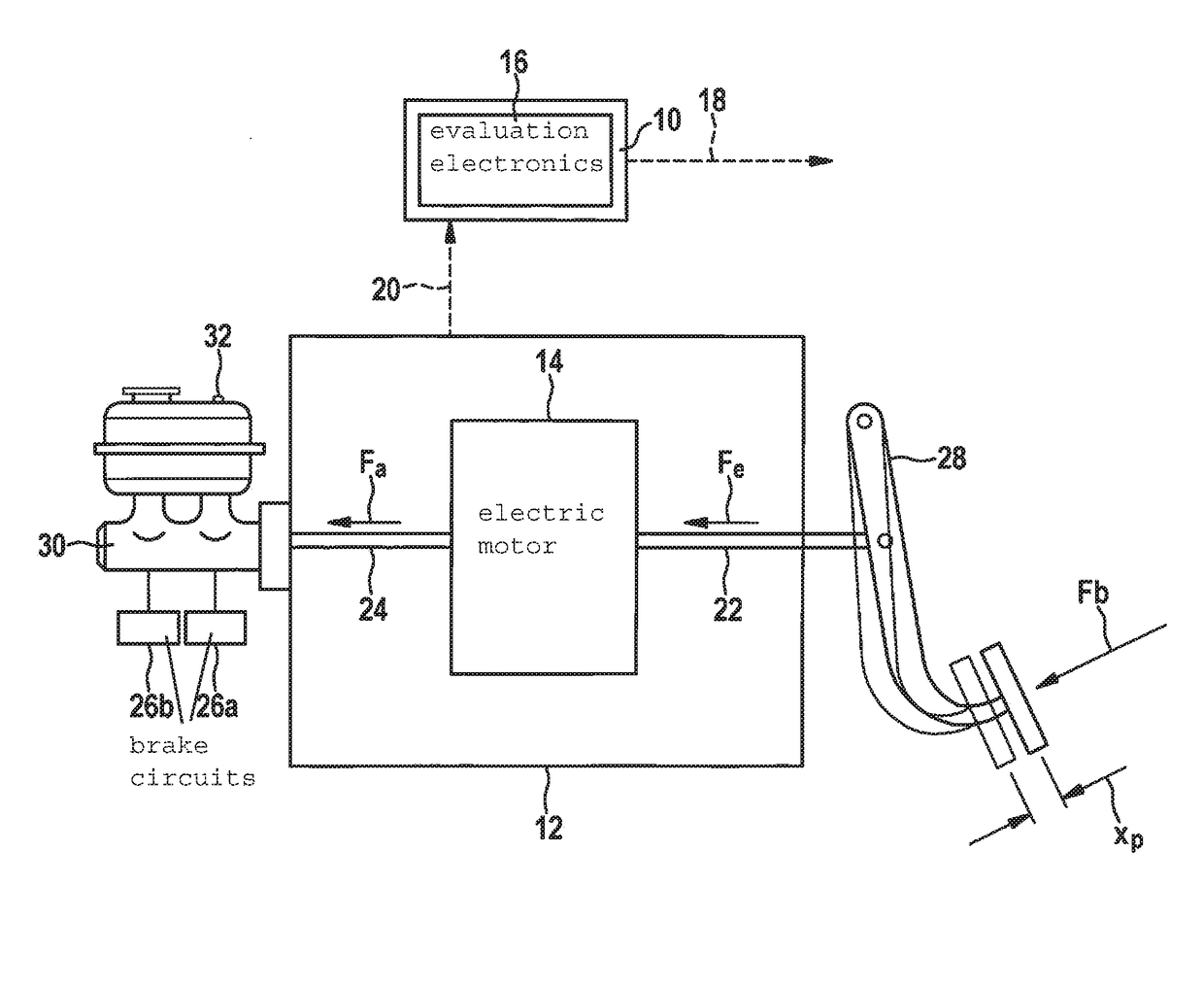
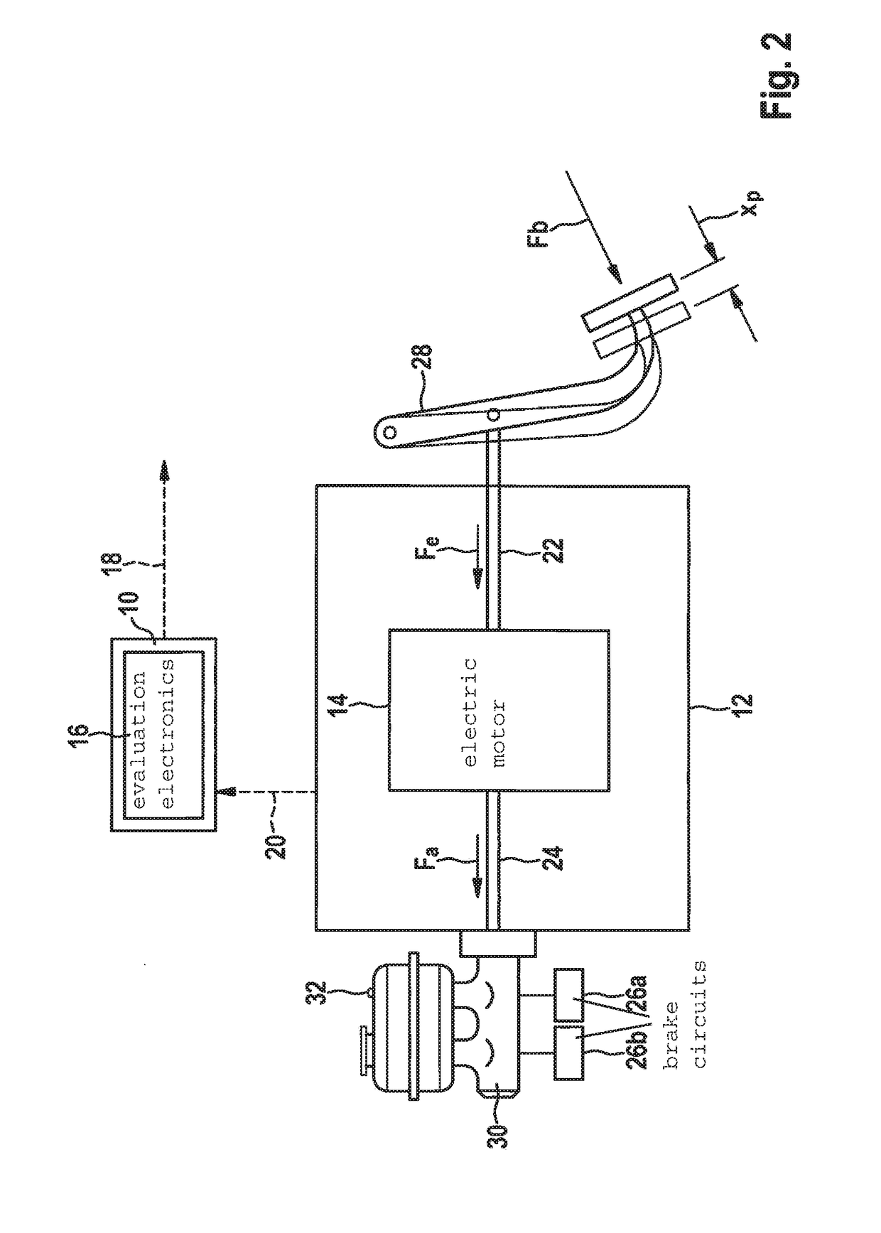
[0024]FIG. 2 schematically shows a depiction of one specific embodiment of the sensor device.

[0025]Sensor device 10 schematically depicted in FIG. 2 is designed to cooperate with a braking system, which is equipped with an electromechanical brake booster 12. Sensor device 10 is preferably installable in and / or on the braking system equipped with electromechanical brake booster 12 or in and / or on a vehicle including the braking system. It is noted that the applicability of sensor device 10 is not limited to a particular type of brake booster or to a particular type of braking system. Thus, any braking system, which includes a brake booster having an (electric) motor 14 definable as an electromechanical brake booster 12, may be equipped with sensor device 10.

[0026]Sensor device 10 includes evaluation electronics 16, which are configured to determine at least one braking request specification variable 18 with respect to a braking request specification of a user of the braking system. I...


PUM


Abstract

A sensor device for a braking system equipped with an electromechanical brake booster, including evaluation electronics, which are configured to determine at least one braking request specification variable, while taking into account at least one actual variable with respect to a functionality of at least one component of the electromechanical brake booster and / or at least one setpoint variable for specifying the functionality of the at least one component of the electromechanical brake booster as a provided variable. A controller for a braking system equipped with an electromechanical brake booster, a braking system for a vehicle, a method for ascertaining a braking request specification variable to a braking system equipped with an electromechanical brake booster, and a method for operating a braking system equipped with an electromechanical brake booster, are also described.

Description

FIELD[0001]The present invention relates to a sensor device for a braking system equipped with an electromechanical brake booster. The present invention also relates to a controller for a braking system equipped with an electromechanical brake booster and to a braking system for a vehicle. In addition, the present invention relates to a method for ascertaining a braking request specification to a braking system equipped with an electromechanical brake booster and to a method for operating a braking system equipped with an electromechanical brake booster.BACKGROUND INFORMATION[0002]A method and a device for operating a braking assistance system are described in German Patent Application No. DE 10 2009 000 294 A1. In order to ascertain whether the braking behavior of the driver is typical for an emergency brake application, a driver primary pressure is measured as a physical variable, which is said to be characteristic of the brake actuation by the driver. To ascertain the driver prim...

Claims


Application Information

Patent Timeline
Patent Type & Authority Applications(United States)
IPC IPC(8): B60T7/04B60T8/172B60T13/74
CPCB60T7/042B60T13/745B60T13/746B60T2220/04B60T2270/10B60T2270/30B60T8/172B60T13/66B60T8/171B60T2270/60B60Y2400/30
Inventor BUNK, MICHAEL
Owner ROBERT BOSCH GMBH
Learn More