
Substrate processing apparatus

a substrate processing and substrate technology, applied in the direction of electrical apparatus, conveyor parts, conveyors, etc., can solve the problems so as to achieve the effect of increasing the footprint (the occupied area) the size of the substrate processing apparatus

Active Publication Date: 2017-09-14
DAINIPPON SCREEN MTG CO LTD
View PDF3 Cites 4 Cited by
  • Summary
  • Abstract
  • Description
  • Claims
  • Application Information

AI Technical Summary

Benefits of technology

The patent aims to provide a substrate processing apparatus that has a smaller footprint, meaning it occupies less space. The current design of the apparatus results in an increased size in the direction of the transfer path, due to the arrangement of the shuttle transfer mechanism, main transfer robot, and raising / lowering drive mechanism. The objective is to reduce the size of the substrate processing apparatus and minimize its footprint.

Problems solved by technology

Therefore, the size of the substrate processing apparatus is increased in the direction in which the transfer path is extended, and thus the footprint (the occupied area) of the substrate processing apparatus may be increased.

Method used


Image

  • Substrate processing apparatus
  • Substrate processing apparatus
  • Substrate processing apparatus

Examples


first preferred embodiment

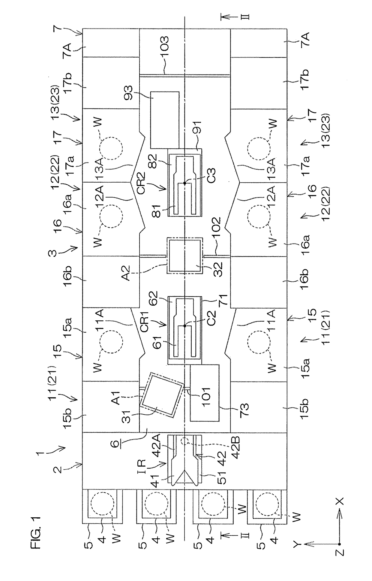
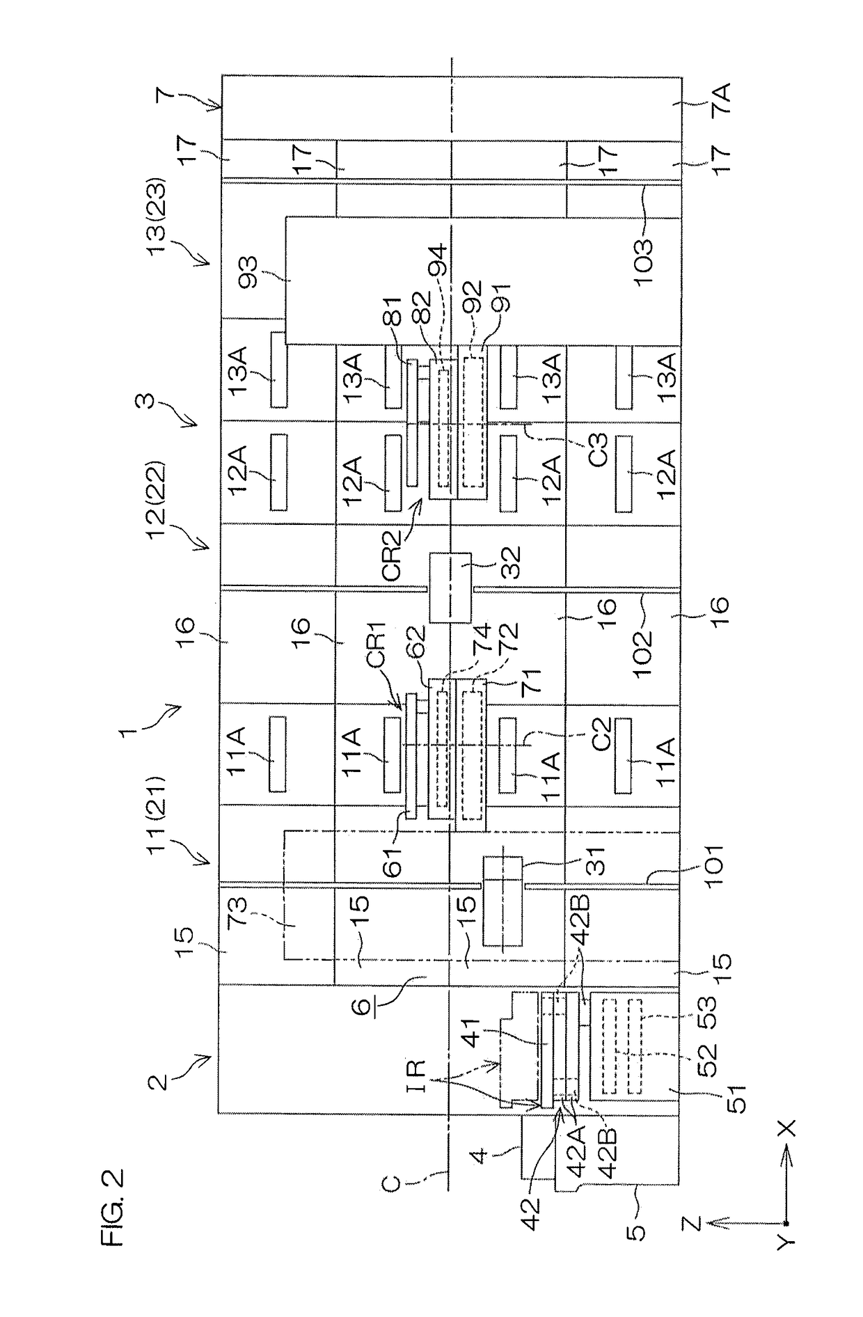
[0036]FIG. 1 is a schematic plan view for illustrating the layout of the interior of a substrate processing apparatus 1 according to a first preferred embodiment of the present invention. FIG. 2 is a schematic vertical cross-sectional view taken along line II-II of FIG. 1.

[0037]The substrate processing apparatus 1 is a single substrate processing-type apparatus which performs various types of processing such as cleaning processing and etching processing on substrates W such as semiconductor wafers one by one. The substrate processing apparatus 1 includes an indexer section 2 which holds an unprocessed substrate W and a processed substrate W, a processing section 3 which processes the substrate W and a power supply section 7 which supplies power to the indexer section 2 and the processing section 3. The indexer section 2, the processing section 3 and the power supply section 7 are aligned along a horizontal direction. The indexer section 2 is adjacent to the processing section 3. The...

second preferred embodiment

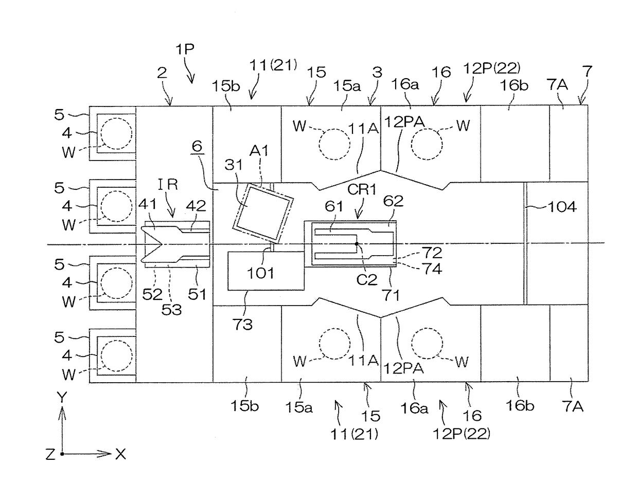
[0115]FIG. 4 is a schematic plan view for illustrating the layout of the interior of a substrate processing apparatus 1P according to the second preferred embodiment. In FIG. 4 and FIG. 5 which will be described later, the corresponding members as those described previously are identified with the same reference signs, and the description thereof will be omitted.

[0116]The substrate processing apparatus 1P according to the second preferred embodiment differs from the substrate processing apparatus 1 according to the first preferred embodiment in that the substrate processing apparatus 1P does not include the second placement unit 32 and that the processing section 3 of the substrate processing apparatus 1P does not include the second processing portions 12, the third processing portions 13 and the second main transfer robot CR2. Hence, the power supply section 7 is adjacent to the first processing portion 11 of the substrate processing apparatus 1P from the side opposite to the index...


PUM


Abstract

A transfer path is provided which is extended so as to be passed on a lateral side of a processing portion that processes a substrate. The substrate transferred between a container held by a holding unit and the processing portion passes through the transfer path. A first transfer robot carries the substrate into and out of the container held by the holding unit, and accesses a reception / delivery region arranged within the transfer path. A second transfer robot receives and delivers the substrate from and to the first transfer robot in the reception / delivery region, and carries the substrate into and out of the processing portion. A second transfer robot raising / lowering unit which raises and lowers the second transfer robot is arranged within the transfer path. The reception / delivery region and the second transfer robot raising / lowering unit are located between the first transfer robot and the second transfer robot.

Description

BACKGROUND OF THE INVENTION[0001]1. Field of the Invention[0002]The present invention relates to a substrate processing apparatus that processes substrates. Examples of substrates to be processed include semiconductor wafers, substrates for liquid crystal display devices, substrates for plasma displays, substrates for FEDs (Field Emission Displays), substrates for optical disks, substrates for magnetic disks, substrates for magneto-optical disks, substrates for photomasks, ceramic substrates and substrates for solar cells.[0003]2. Description of the Related Art[0004]An example of a single substrate processing-type substrate processing apparatus which is used in the manufacturing process of a semiconductor device is disclosed in Japanese Patent Application Publication No. 2006-332543. The apparatus includes a carrier holding portion which holds a carrier that can be contained in a state where a plurality of substrates are stacked in layers, a processing portion which processes the su...

Claims


Application Information

Patent Timeline
Patent Type & Authority Applications(United States)
IPC IPC(8): H01L21/687H01L21/677H01L21/67
CPCH01L21/68707H01L21/67023H01L21/67712H01L21/67184H01L21/67748H01L21/67751H01L21/67167H01L21/67011H01L21/67742H01L21/67161H01L21/67173H01L21/67178H01L21/6773B65G47/90B65G49/061H01L21/67745H01L21/67772B65G2201/022H01L21/67703
Inventor MURAMOTO, RYO
Owner DAINIPPON SCREEN MTG CO LTD
Learn More