
Substrate type antenna

a substrate and antenna technology, applied in the direction of antennas, antenna feed intermediates, antenna details, etc., can solve problems such as interference, and achieve the effect of minimizing the space between the antennas and the substrate's siz

Active Publication Date: 2017-12-21
NISSEI LTD
View PDF4 Cites 4 Cited by
  • Summary
  • Abstract
  • Description
  • Claims
  • Application Information

AI Technical Summary

Benefits of technology

The present invention provides a substrate type antenna that can achieve small-sizing while preventing interference between two antennas that have almost the same resonance frequency. The invention solves the problem of interference by positioning the two antennas close to each other, but without their resonance frequencies shifting. The invention also provides a spiral antenna pattern that can be rotated on a substrate to further reduce interference between the two antennas. The invention further includes a structure with multiple spiral antenna patterns and gaps, which enhances the ability to position the two antennas close to each other without interference. Overall, the invention provides a small-sized substrate type antenna that minimizes interference between antennas and maximizes performance.

Problems solved by technology

However, in the case where the MIMO communication is achieved by using the substrate type antenna, if applying such two (2) pieces of substrate type antennas of the linear polarization type therein, as is described in the Patent Document 1, an interference occurs, in particular when both the antennas are arranged to be close to or neighboring with each other, i.e., a matching frequency being shifted.

Method used


Image

  • Substrate type antenna
  • Substrate type antenna
  • Substrate type antenna

Examples


embodiment 1

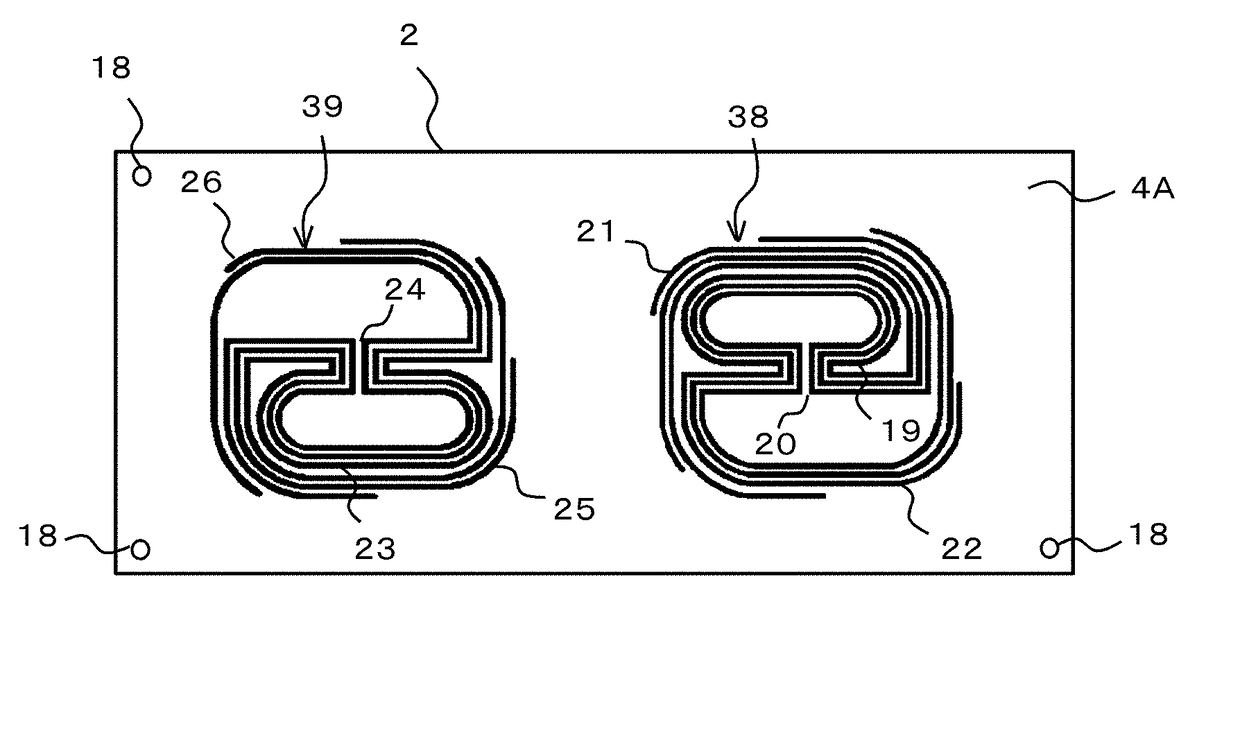
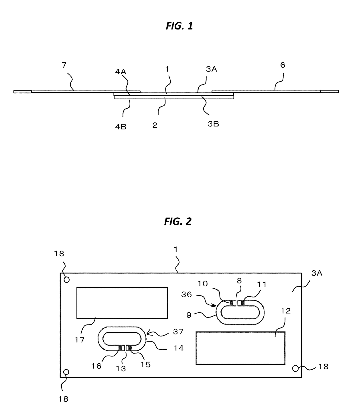
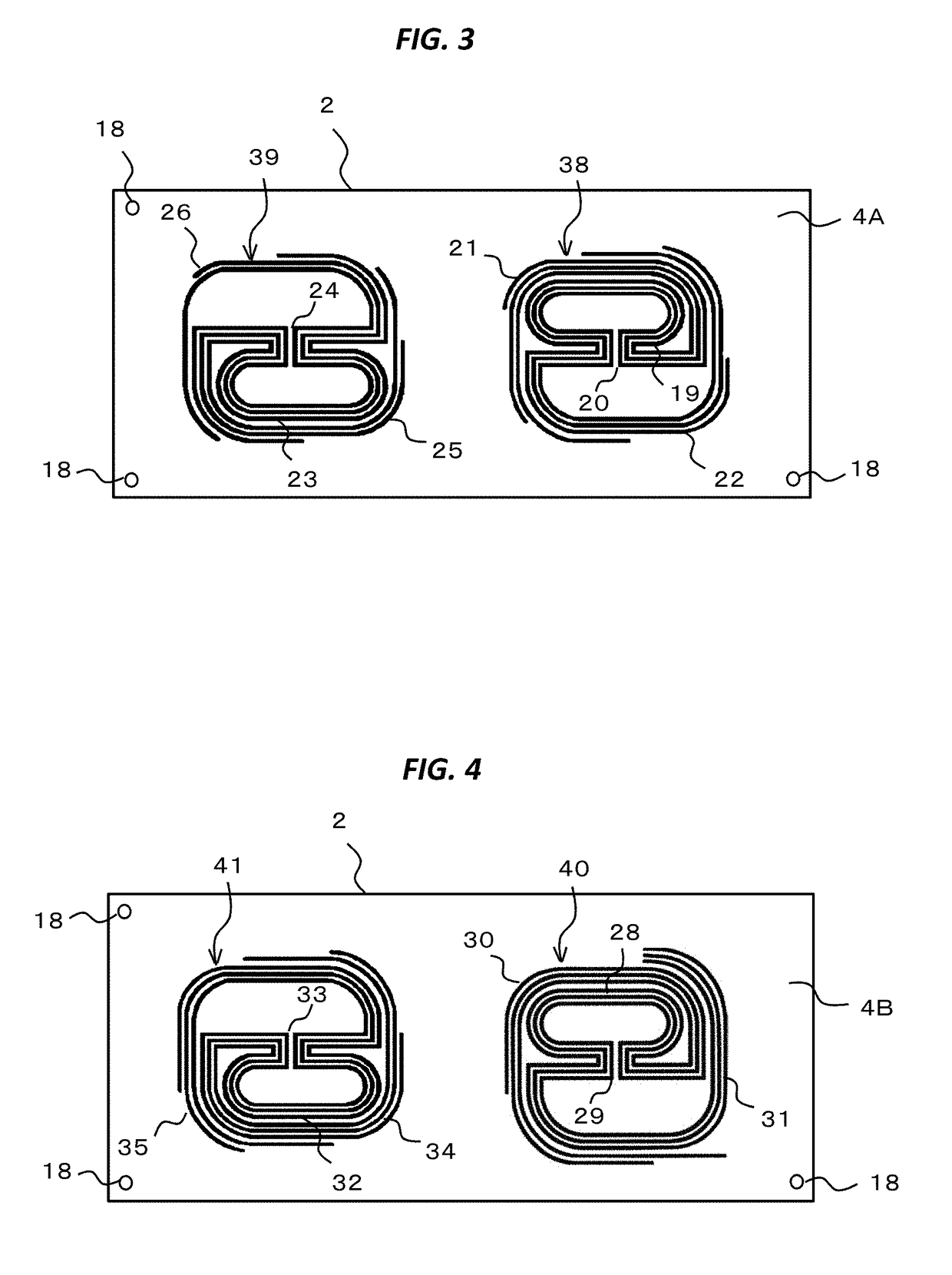
[0044]The substrate type antenna according to the present embodiment, to be structured for use in the MIMO communication of the 800 MH band, comprises a main antenna, including a first antenna for use of LTE communication and an antenna for use of GPS, and also a sub-antenna. The first antenna is used as an antenna for transmitting / receiving a single of a resonance frequency band of 815-875 MHz, while the sub-antenna is used for receiving a signal of resonance frequency band of 815-875 MHz.

[0045]FIG. 1 is a side view for showing the substrate type antenna, according to the embodiment of the present invention.

[0046]Two (2) pieces of substrates 1 and 2 are piled up or laminated, wherein a substrate surface 3A is formed on the side of an upper surface of the substrate 1, while a substrate surface 3B is formed on the side of a lower surface of the substrate 1. In the similar manner, on the side of the upper surface of the substrate 2 is formed a substrate surface 4A, while on the side o...

embodiment 2

[0083]FIG. 12 is a side view for showing the substrate type antenna according to other embodiment of the present invention.

[0084]Two (2) pieces of substrates 45 and 46, each having height of 35 mm, width of 35 mm, and thickness of 0.4 mm, approximately, are laminated. On an upper side surface of the substrate 45 is formed a substrate surface 47, and on a lower side surface of the substrate 45 is formed a substrate surface 48, respectively. Also, on an upper side surface of the substrate 46 is formed a substrate surface 49, and on a lower side surface of the substrate 46 is formed a substrate surface 50, respectively. Between the substrate surface 48 of the substrate 45 and the substrate surface 49 of the substrate 46 is arranged a spacer 51. Because of insertion of this, it is possible to shorten or reduce the distance between the antenna patterns.

[0085]FIG. 13 is a plane view for showing the enlarged substrate surface.

[0086]On the substrate surface 48 of the substrate 45 seen from ...


PUM


Abstract

A substrate type antenna for conducting signal transmitting / receiving with using two (2) antennas, each having almost same resonance frequency, wherein each of those two (2) antennas applies therein a spiral antenna having an antenna side coupling pattern, which is positioned to face to a power supply point side coupling patter, and a spiral antenna having a spiral antenna pattern, which is coupled to the antenna side coupling pattern, and wherein those two (2) antennas are positioned in such a manner that extending directions of the facing end portions, being closest to each other in the spiral antenna patterns of those two (2) antennas, are not aligned to each other, but are shifted in different directions.

Description

TECHNICAL FIELD OF THE INVENTION[0001]The present invention relates to a substrate type antenna including two (2) antennas, each having a resonance frequency band being almost same to.BACKGROUND OF THE INVENTION[0002]Such as in case of MIMO communication (Multi Input Multi Output) is already known structure of arranging two (2) or more antennas neighboring with each other, and thereby achieving high-speed communication. As a substrate type antenna according to the conventional art is already known that having a substrate made of dielectric material, a loop-shaped first coupling pattern formed on one of the surfaces of this substrate, being cut off in apart thereof, and a loop-shaped second coupling pattern formed on the other surface of the substrate, being cut off in a part thereof, and also connecting the respective power supply points to the both ends, which are divided, wherein couplings of dielectric coupling and magnetic inductive coupling are made between the first coupling p...

Claims


Application Information

Patent Timeline
Patent Type & Authority Applications(United States)
IPC IPC(8): H01Q1/38H01Q9/27H01Q3/12H01Q25/00H01Q1/52
CPCH01Q1/38H01Q9/27H01Q25/00H01Q3/12H01Q1/523H01Q21/28
Inventor KANEKO, TSUTOMUKARAKAMA, TAKAHISA
Owner NISSEI LTD
Learn More