
Water collecting pallet rack and method of fire protection

a pallet rack and water collection technology, applied in the field of pallet rack storage systems, can solve the problems of difficult water spraying from an overhead fire sprinkler system, difficult to extinguish warehouse fires, and unchecked fires that can quickly destroy these valuable articles either directly or collaterally, and achieve the effect of improving the wetting of articles

Active Publication Date: 2017-09-07
FIREBIRD SPRINKLER COMPANY
View PDF2 Cites 10 Cited by
  • Summary
  • Abstract
  • Description
  • Claims
  • Application Information

AI Technical Summary

Benefits of technology

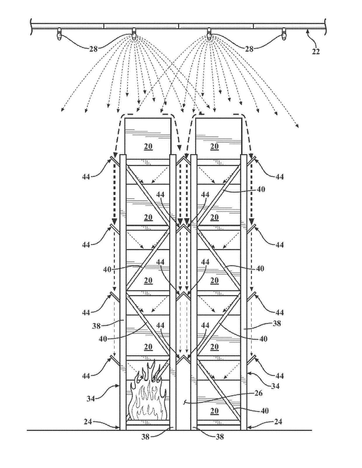
This patent describes an improved storage rack system for articles that helps to quickly wet the articles in the event of a fire. The system uses a wetting zone of an overhead fire sprinkler system and is designed to work with existing fire suppression systems. The rack system includes multi-tiered shelves made up of horizontal beams that are offset from each other. The rack is combined with a falling water collection system that collects water and channels it quickly towards the inner parts of the rack to help with fire suppression. Overall, this system helps make fire suppression systems more efficient by transforming flues into firefighting agents.

Problems solved by technology

An unchecked fire can quickly destroy these valuable articles either by direct combustion, or collaterally be heat, smoke or water damage.
Furthermore, articles stacked in rack arrays usually offer an abundant fuel source for a fire to grow and quickly propagate, making warehouse fires especially difficult to extinguish.
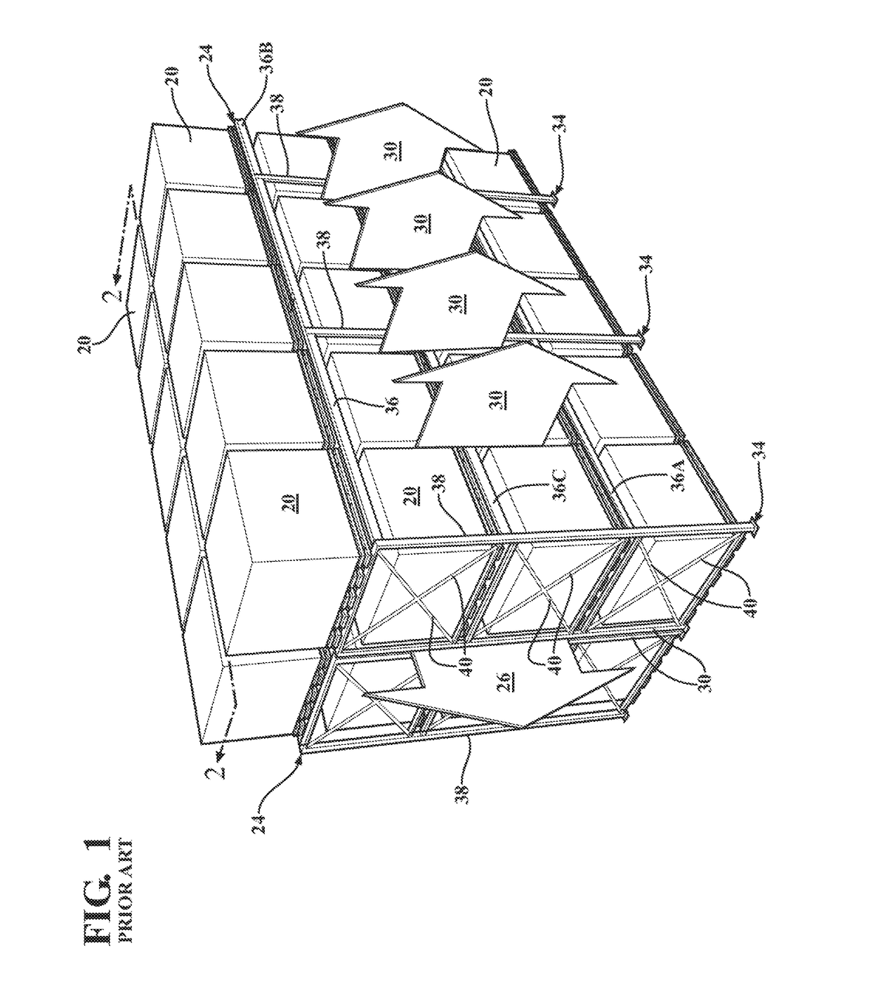
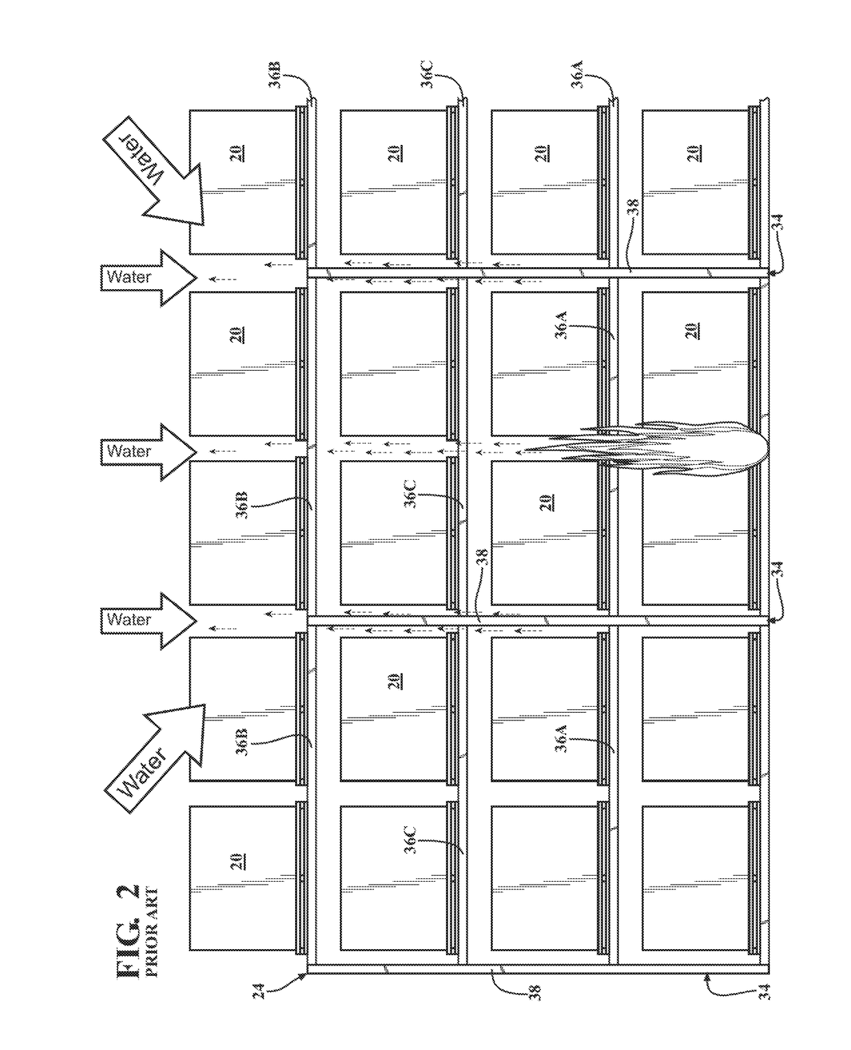
This objective is often frustrated in warehouse storage settings due to the fact that stacked or arranged rows of articles tend to make it difficult for water sprayed from an overhead fire sprinkler system to reach a fire starting deep inside a rack array near the floor.
When a fire originates in or near the longitudinal flue, it is very difficult to reach the fire with water dispersed from an overhead fire sprinkler.
Furthermore, a surprisingly large percentage of water issuing from overhead sprinklers lands uselessly on the floor rather being usefully applied to combat a fire or wet surrounding objects in jeopardy.
A majority of the run-off water is expected to fall uselessly to the floor.
As a result, in prior art fire suppression systems, a near-ground fire typically grows rapidly inside a rack array with little to no direct exposure to the sprayed water until the fire has grown large and powerful and set ablaze many levels of articles.
In-rack sprinkler systems are notoriously expensive to install, and are prone to frequent damage from collisions as articles are frequently moved into and out of the rack arrays during normal warehousing activities.
And yet another drawback of in-rack systems is the constraint imposed on future remodeling efforts.
That is to say, once an in-rack sprinkler systems is installed, a warehouse manager will be reluctant to rearrange the location of the affected rack arrays due to the integrated plumbing.
Thus, in-rack sprinkler systems are not an attractive solution, but compared to the catastrophic prospect of fire in a warehouse are used with some frequency.
Another problem with in-rack sprinkler systems pertains to the distribution of water inside rack arrays.
In particular, water forcefully discharged from a sprinkler head located deep inside (e.g., in a longitudinal flue) of a rack array will tend to explosively splash and ricochet, without much opportunity for thoughtful guided placement of water.
This sheltering of the spray heads severely compromised the spray pattern.
While this concept may have helped better distribute water from the in-rack system, still no benefit is provided to water discharged from overhead sprinklers whose run-off continues to cascades over the sides and fall uselessly to the floor.

Method used


Image

  • Water collecting pallet rack and method of fire protection
  • Water collecting pallet rack and method of fire protection
  • Water collecting pallet rack and method of fire protection

Examples


Embodiment Construction

[0036]Referring to the figures, wherein like numerals indicate like or corresponding parts throughout the several views, the invention is set in the context of an open framework type of warehouse storage rack system for supporting articles 20 on multi-tiered shelves within the wetting zone of an overhead fire sprinkler system 22 (e.g., FIG. 4). The storage rack may comprise any of various forms of industrial racking including, but not limited to, pallet racks, cantilever racks, picker racks, conveyor racks and drive-in racks to name a few. For consistency, the following descriptions and accompanying illustrations generally portray the storage rack system as a common pallet-type rack structure, however the invention is intended to be generally applicable to many different types of industrial racking configurations.

[0037]Furthermore, the storage rack may exist as a single, stand-alone longitudinally-extending rack array 24 accessible from both sides (e.g., FIG. 17), or as two back-to-...


PUM

PropertyMeasurementUnit
Wetting tensionaaaaaaaaaa

Abstract

An open framework warehouse storage rack system for supporting articles on multi-tiered shelves within the wetting zone of an overhead fire sprinkler system. The storage rack system comprises one or more a longitudinally extending rack arrays. A falling water collection system is combined with some or all of the rack arrays. The falling water collection system includes any one of several water handling features that enhance the wetting of storage articles during a fire. One such feature is a scoop-like longitudinal water catcher that protrudes outwardly beyond the front and / or rear faces of the rack array. Another is a transverse intra-stanchion water diverter. Another is a transverse mid-span water diverter. Another is a gutter formed integrally in an uppermost beam. And another is a vertical flue catcher. The falling water collection system maximizes the amount of water that is applied directly to a fire inside the rack array.

Description

CROSS REFERENCE TO RELATED APPLICATIONS[0001]This application claims priority to Provisional Patent Application No. 62 / 303,857 filed Mar. 4, 2016, the entire disclosure of which is hereby incorporated by reference and relied upon.BACKGROUND OF THE INVENTION[0002]Field of the Invention[0003]The invention relates generally to systems and methods for extinguishing fires, and more particularly to a pallet rack storage system specially configured to suppress in-rack fires.[0004]Description of Related Art[0005]Articles stored in warehouses usually represent a significant capital investment in either raw, partially finished or finished good / inventory. In a warehouse, articles—sometimes palletized—are frequently stacked in multi-tiered rack arrays, which in turn are arranged in long rows. An unchecked fire can quickly destroy these valuable articles either by direct combustion, or collaterally be heat, smoke or water damage. Furthermore, articles stacked in rack arrays usually offer an abun...

Claims


Application Information

Patent Timeline
IPC IPC(8): A62C3/00A47B81/00A47B97/00B05B1/26B65G1/02
CPCA62C3/002B05B1/26A47B81/00A47B97/00B65G1/02A47B47/0083A47B47/021A47B55/00B65G2207/22
Inventor PIGEON, JEFFREY J.
Owner FIREBIRD SPRINKLER COMPANY
Learn More