
Real-time payment system, method, apparatus, and computer program

a real-time payment and payment method technology, applied in the field of electronic real-time payment and non-payment transactions, can solve the problems of not providing a service with real-time crediting and settlement capability, consumers still burdened, and affecting the capture of all possible banking related revenu

Pending Publication Date: 2017-08-03
THE CLEARING HOUSE PAYMENTS
View PDF2 Cites 58 Cited by
  • Summary
  • Abstract
  • Description
  • Claims
  • Application Information

AI Technical Summary

Benefits of technology

The real-time payments system is a secure and efficient system for making purchases and paying bills in real-time. It uses advanced technology to reach financial institutions and offer them the ability to provide innovative payment services to their customers. The system is designed to be easily extended and secure, with features like promotions and rewards for customers. Overall, this patent makes a case for the benefits of real-time payments in making retail transactions more efficient and customer-friendly.

Problems solved by technology

Indeed, payment revenue is increasingly targeted by non-banks, and, missing out on these fees could detrimentally impact the capture of all possible banking related revenue.
Financial transfers today take place more quickly than before, but consumers are still burdened with needing to review their accounts to identify unauthorized or false transactions, and disputing such transactions with their financial institutions.
However, none of those services actually provide a service with a real-time crediting and settlement capability (i.e., posting of funds immediately to a creditor's account).
By not having debits, the risk of a reversal due to fraudulent and / or unauthorized debits is removed.
Also, currently, in the case of a payment error, existing processes for returning funds are manual, costly, and unsatisfying for consumers.

Method used


Image

  • Real-time payment system, method, apparatus, and computer program
  • Real-time payment system, method, apparatus, and computer program
  • Real-time payment system, method, apparatus, and computer program

Examples


Embodiment Construction

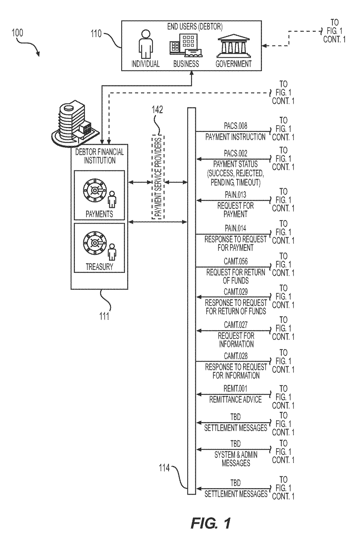
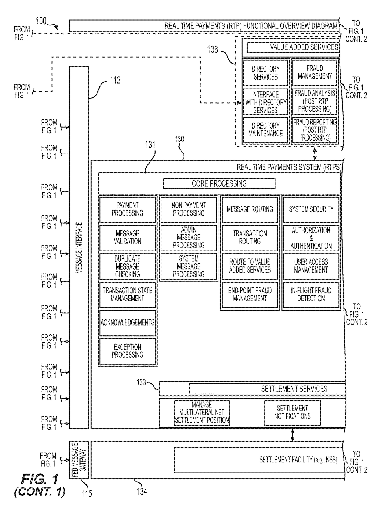
[0108]FIG. 1 is a diagram of a transaction system 100 configured in accordance with an example embodiment herein. The transaction system 100 includes user stations 110 and 121. In an example embodiment, user station 110 is operated by, under the authorization of, or on behalf of a debtor (e.g., an individual, business, government, etc.), and user station 121 is operated by, under the authorization of, or on behalf of a creditor (e.g., an individual, business, government, etc.). In this example, the debtor may owe one or more debts to the creditor. Accordingly, user station 110 can be referred to as a “debtor station,” and user station 121 can be referred to as a “creditor station.” Each user station may be, for example, a personal computer, a tablet computer, a smartphone, a standalone computer terminal such as a kiosk or ATM, or any other suitable type of electronic device for receiving, transmitting, storing, and / or processing information.

[0109]The transaction system 100 also incl...


PUM


Abstract

A method, system, apparatus, and computer program for conducting a real-time payment settlement transaction. The method includes determining a prefunded requirement for one or more financial institutions. A prefunded balance is stored, based on a prefunded payment received in a separate funding account, for each of the one or more financial institutions. The method further includes receiving an electronic request for payment message from at least one creditor financial institution, and forwarding the electronic request for payment message to at least one debtor financial institution, the electronic request for payment message requesting that a payment be made to the at least one creditor financial institution and comparing the amount of payment requested in an electronic payment transaction to the prefunded balance of the at least one debtor financial institution. A real-time financial settlement transaction is performed based on a result of the comparing step.

Description

CROSS REFERENCE TO RELATED APPLICATION[0001]The present application is a continuation-in-part of copending U.S. patent application Ser. No. 15 / 200,340, filed Jul. 1, 2016, which is incorporated by reference in its entirety, and which claims priority to U.S. Provisional Patent Application No. 62 / 187,406, filed Jul. 1, 2015, and U.S. Provisional Patent Application No. 62 / 286,738, filed Jan. 25, 2016, the contents of which are also incorporated by reference herein in their entirety, as if set forth fully herein.BACKGROUND[0002]Field[0003]Example aspects herein relate generally to electronic transactions and, more specifically, to electronic real-time payment and non-payment transactions.[0004]Description of the Related Art[0005]The average banking customer interacts with his or her bank or financial institution at least twice a day for payment-related matters, such as buying a financial product, checking on a payment, or paying a bill. These interactions represent more than 80 percent ...

Claims


Application Information

Patent Timeline
Patent Type & Authority Applications(United States)
IPC IPC(8): G06Q20/40
CPCG06Q20/4037G06Q20/407G06Q20/4016
Inventor LEDFORD, STEPHENAHMAD, IRFAN
Owner THE CLEARING HOUSE PAYMENTS
Learn More