
Feed shaft control method and numerically controlled machine tool

a control method and machine tool technology, applied in the direction of electric programme control, program control, instruments, etc., can solve the problems of increased machining error, long machining time, and increased machining error in servo control, so as to increase cutting efficiency and machining accuracy.

Active Publication Date: 2017-08-03
MAKINO MILLING MASCH CO LTD
View PDF2 Cites 0 Cited by
  • Summary
  • Abstract
  • Description
  • Claims
  • Application Information

AI Technical Summary

Benefits of technology

This invention aims to improve the control of a feed axis in a numerically controlled machine tool. The goal is to reduce the impact caused by changes in acceleration and deceleration, and to machine workpieces at high speed and with high accuracy. The invention compensates for the accelerations present in move commands by driving a micro-motion device, which allows for increased acceleration and deceleration of the feed axes. This results in improved machining accuracy and cutting efficiency.

Problems solved by technology

Pre-interpolation acceleration / deceleration controls, as described in Patent Literatures 1 and 2, involve a problem that the acceleration / deceleration time is elongated, resulting in the longer machining time.
Further, post-interpolation acceleration / deceleration controls involve a problem that when two or more feed axes are simultaneously controlled in order to machine for example a corner portion in the X-Y plane, the machining error is increased since the actual tool path extends along an inner arcuate course compared with a tool path based on the move commands before the acceleration / deceleration control.
Composite servo systems, as described in Patent Literature 3, involve a problem that mutually interfering forces are generated between the coarse and fine positioners due to the movement relative to each other, resulting in errors in the servo-control.

Method used


Image

  • Feed shaft control method and numerically controlled machine tool
  • Feed shaft control method and numerically controlled machine tool
  • Feed shaft control method and numerically controlled machine tool

Examples


first embodiment

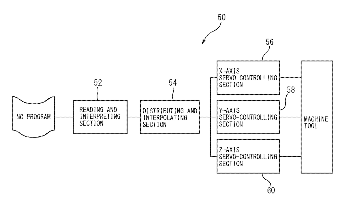
[0037]With reference to FIG. 5, the servo-control device 100 according to the invention includes, similar to conventional servo-control devices, an acceleration / deceleration filter 102 for position commands Xs from the distributing and interpolating section 54, a subtractor 104 for comparing the position commands from the acceleration / deceleration filter 102 and position feedback signals from the X-axis scale 48, a position controller 106 for performing a differential operation on the outputs from the subtractor 104, a subtractor 108 for comparing the outputs from the position controller 106 and velocity feedback signals from the rotary encoder of the X-axis servomotor 28, a velocity controller 110 for performing a differential operation on the signals from the subtractor 108, a current controller 112 for controlling the electric current output to the X-axis servomotor 28 based on the outputs from the velocity controller 110, a velocity feedforward controller 114 and an acceleration...

second embodiment

[0041]With reference to FIG. 7, a servo-controlling device 200 according the the invention includes, similar to conventional servo-controlling devices, a subtractor 202 comparing the position commands X0 from the distributing and interpolating section 54 and the position feedback signals from the X-axis scale 48, a position controller 204 for performing a differential operation on the outputs from the subtractor 202, a subtractor 206 for comparing the outputs from the position controller 204 and the velocity feedback signals from the rotary encoder 28a of the X-axis servomotor 28, a velocity controller 208 for performing a differential operation on the outputs from the velocity controller 208, a current controller 210 for controlling the electric current output to the X-axis servomotor 28 based on the outputs from the velocity controller 208, a velocity feedforward controller 212 and an acceleration feedforward controller 214 for generating velocity feedforward values and accelerati...


PUM


Abstract

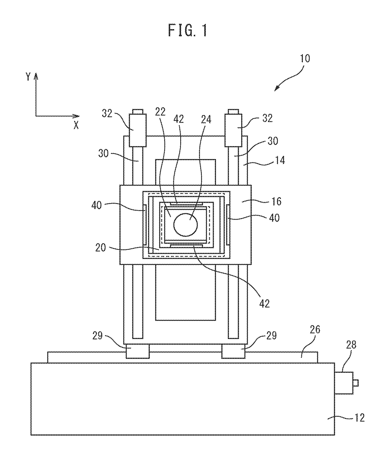
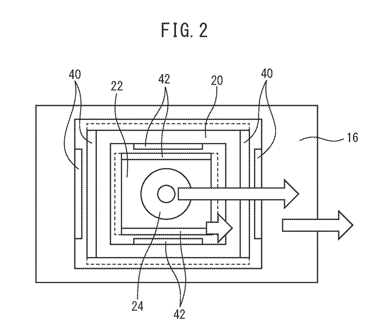
A numerically controlled machine tool in which a numerical control program acquired from a reading and interpreting unit of a numerical control device is executed by a distribution interpolating unit and servo control units, to drive a feed shaft configured from a coarse movement mechanism and a fine movement mechanism, causing a tool to move relative to a workpiece, and thereby machining the workpiece, wherein the difference between a movement command for the feed shaft, and an output value which varies on the basis of said movement command is obtained, a movement command for the coarse movement mechanism is generated on the basis of said movement command, and a movement command for the fine movement mechanism is generated on the basis of said difference.

Description

CROSS-REFERENCE TO RELATED APPLICATIONS[0001]This application is a U.S. National Stage patent application of International Patent Application No. PCT / JP2014 / 076220, filed on Sep. 30, 2014, which is hereby incorporated by reference in the present disclosure in its entirety.FIELD OF THE INVENTION[0002]The invention relates to a method of controlling a feed axis of a machine tool and a numerically controlled machine tool configured to carry out the feed axis controlling method.BACKGROUND OF INVENTION[0003]In the control of a feed axis of a machine tool, when carrying out machining commands, impacts may be generated at parts of the machine tool due to sudden changes in the velocities of the feed axes. In order to reduce such impacts, an acceleration / deceleration control for feed axes is performed. The acceleration / deceleration control includes for example a post-interpolation acceleration / deceleration control wherein move commands, from a distributing and interpolating section of a nume...

Claims


Application Information

Patent Timeline
Patent Type & Authority Applications(United States)
IPC IPC(8): G05B19/404B23Q15/013H02P27/00B23Q15/007
CPCG05B19/404B23Q15/007G05B2219/41154H02P27/00B23Q15/013G05B19/416H02P6/16H02P23/12G05B2219/42225
Inventor ODA, MITSUNARI
Owner MAKINO MILLING MASCH CO LTD
Learn More