
Suspension For Aircraft Tail Wheel

a technology for aircraft tail wheels and suspension systems, which is applied in the direction of wheel arrangements, alighting gear, transportation and packaging, etc., can solve the problems of tail wheel shimmy, other problems in the suspension system of leaf springs, and adversely affect the control of aircraft, so as to achieve the effect of cushioning forces

Active Publication Date: 2017-08-03
DUFAULT DANIEL ROGER
View PDF23 Cites 13 Cited by
  • Summary
  • Abstract
  • Description
  • Claims
  • Application Information

AI Technical Summary

Benefits of technology

The present invention is a new system that replaces the traditional leaf spring suspension in small aircraft. It uses a shock absorber and a coil spring to absorb forces from the tail wheel when it engages the runway. This results in smoother transfer of forces to the pilot and passengers, and reduces the bouncing effect caused by non-resilient leaf springs. The system allows for adjustment of the amount of force needed to compress the shock absorbers and coil spring, and provides better cushioning during landing. Overall, it improves the performance of small aircraft and eliminates the need for a heavy leaf spring assembly.

Problems solved by technology

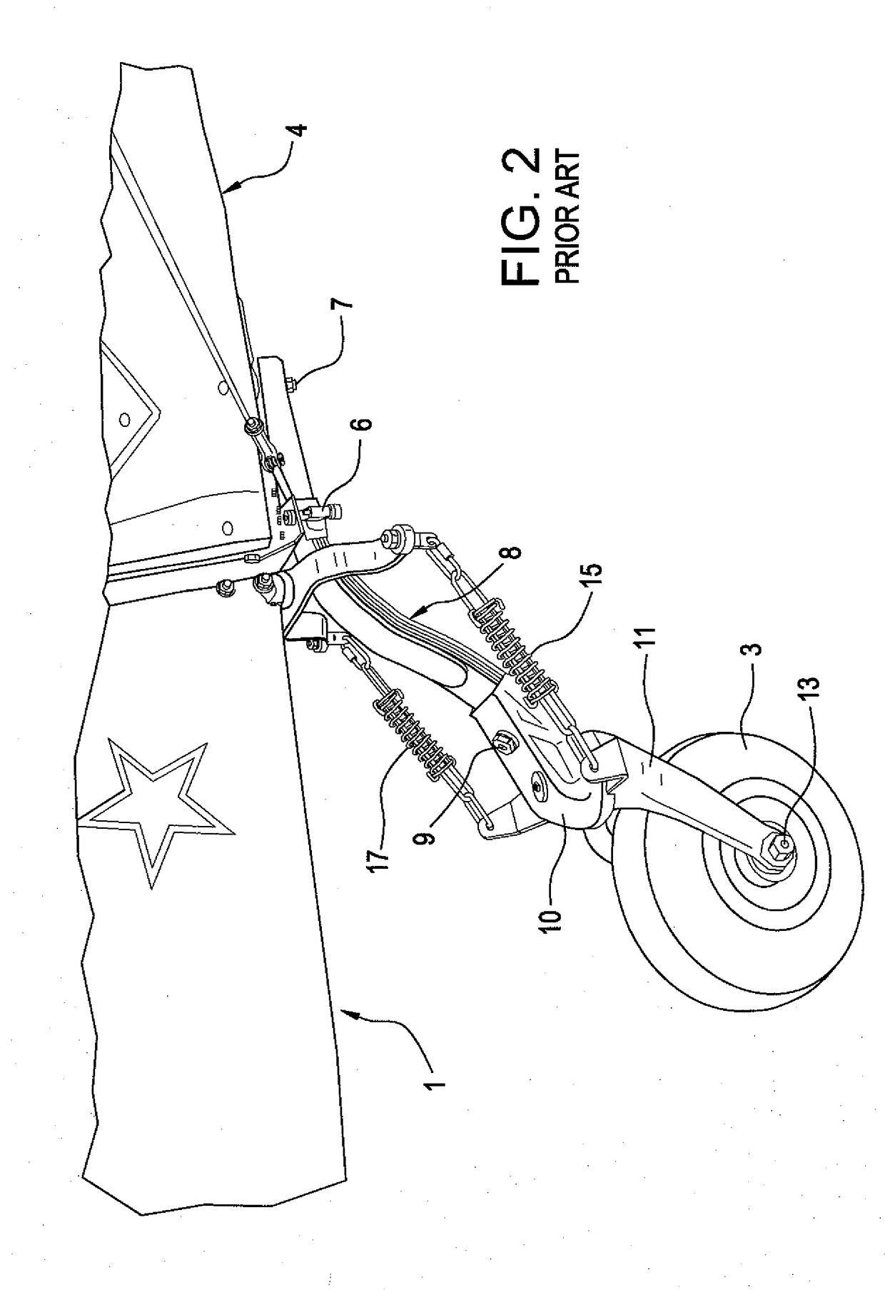
In the prior art, small aircraft typically include a tail wheel that engages the ground during takeoff and, when the aircraft is landing, re-engages the ground with a “bump” that may be severe.
Other problems arise in the leaf spring suspension systems.
As a result, tail wheel shimmy can result.
This shimmying of the tail wheel can adversely impact control of the aircraft while at the same time causing vibrations that can damage the fuselage.
This can be time consuming, labor intensive, and expensive.
Another problem encountered in an aircraft tail wheel is that it is typically pneumatic.
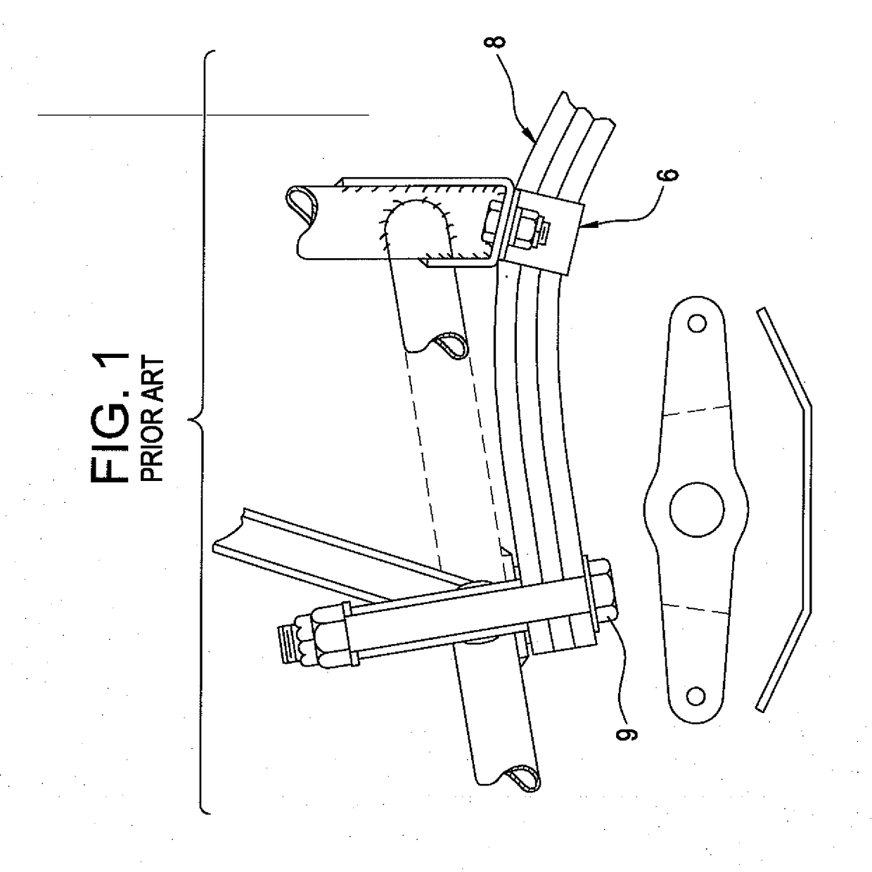
Rather, they are so stiff that when the wheel 3 engages the runway, little cushioning takes place and forces are transmitted from the wheel 3 to the fuselage 4 causing stresses to the fuselage 4 which can result in structural damage.
In fact, typically the tail wheel bounces several times in a bouncing effect, until the bouncing dissipates due to the lack of resiliency of the leaf springs.
Typically, the leaf springs lose their arched configuration over time such that the tail wheel becomes misaligned with respect to the geometry of the aircraft.
The only solution is expensive leaf spring replacement.

Method used


Image

  • Suspension For Aircraft Tail Wheel
  • Suspension For Aircraft Tail Wheel
  • Suspension For Aircraft Tail Wheel

Examples


Embodiment Construction

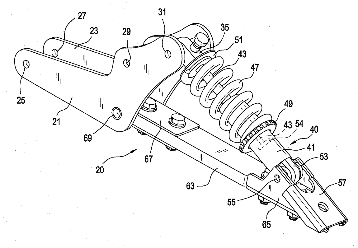
[0028]Reference is first made to FIGS. 3a-6 which depict a first embodiment of the present invention in which a single shock absorber is included. The first embodiment is generally designated by the reference numeral 20 and is seen to include parallel L-shaped brackets 21 and 23 having holes 25, 27, 29, 31 and holes 30 and 33 (FIG. 3b) opposed to the holes 29 and 31, respectively. The holes 25 and 27 facilitate mounting the device 20 on the fuselage of an aircraft. The holes 31 and 33 (FIG. 3b) mount a shaft 37 (FIG. 3b) allowing pivoting of the attachment end 35 of a shock absorber 40 having a cylinder 41 and a piston 54 (shown in phantom in FIG. 3) attached to a piston rod 43. The piston rod 43 is attached to the attachment end 35 and is constrained to move therewith. A compression coil spring 47 extends between a disk 49 permanently affixed to the outer walls of the cylinder 41 and a further disk 51 attached to the attachment end 35. The cylinder 41 has a U-shaped bracket 53 that...


PUM


Abstract

A reciprocating shock absorber combined with a coil spring are interposed between the fuselage of an aircraft and the tail wheel. When the tail wheel engages the runway, its attachment pivots, thereby compressing the shock absorber and the coil spring. This results in smooth transfer of forces from the tail wheel to the fuselage and to the pilot and passengers. If desired, one or more tension springs may counteract the forces imposed by the coil spring to restore the extended configuration of the coil spring and shock absorber.

Description

[0001]The present invention relates to an improved suspension for aircraft tail wheel. Applicant claims priority from Provisional Application Ser. No. 62 / 288,644, filed Jan. 29, 2016.BACKGROUND OF THE INVENTION[0002]In the prior art, small aircraft typically include a tail wheel that engages the ground during takeoff and, when the aircraft is landing, re-engages the ground with a “bump” that may be severe. Prior art small aircraft typically include what is supposed to be a shock absorbing system consisting of leaf springs. There are primarily two types of aircraft that employ tail wheel leaf springs. The first is an aircraft having an aluminum outer shell riveted to bulkheads and stringers. The second type has an airframe made of tubular inner structure covered with fabric. The present invention comprises an effective replacement of the tail wheel suspension of either type.[0003]In this regard, reference is made to FIGS. 1 and 2 which show the prior art leaf spring system. An aircra...

Claims


Application Information

Patent Timeline
IPC IPC(8): B64C25/62B64C25/36
CPCB64C25/36B64C25/62
Inventor DUFAULT, DANIEL ROGER
Owner DUFAULT DANIEL ROGER
Learn More