Vehicle powder coating system

Inactive Publication Date: 2005-08-16
ABB INC
View PDF46 Cites 52 Cited by
  • Summary
  • Abstract
  • Description
  • Claims
  • Application Information

AI Technical Summary

Benefits of technology

[0012]It is therefore among the objectives of this invention to provide a powder spraying system for applying powder coating material onto large objects such as automotive or other vehicle bodies which is capable of transmitting large quantities of powder material over long distances at relatively high flow rates while maintaining the desired density and particle distribution, which is capable of automatically maintaining the appropriate volume of powder coating material within the system irrespective of demand, which efficiently collects and recovers large quantities of oversprayed powder for recirculation, which avoids the accumulation of excessive levels of fines, and, which is comparatively easy to service.
[0016]In an alternative embodiment, the reclaim hopper and primary hopper are each connected to a mixing hopper located within the powder kitchen. Powder pumps within the primary and reclaim hoppers transfer a selected ratio of virgin powder and reclaim or oversprayed powder into the mixing hopper where such powders are intermixed in preparation for transfer to spray guns associated with the spray booth. In accordance with a method of this invention wherein particle size distribution within the powder contained in the mixing hopper is mathematically predicted, the supply of virgin and reclaim powder introduced into the mixing hopper, is controlled so that the volume percentage of fines contained within the mixing hopper does not exceed a predetermined maximum percentage. This ensures stable operation of the powder coating system when applying reclaim or oversprayed powder onto objects within the booth.
[0017]It has been found that large quantities of powder coating material, e.g. on the order of 300 pounds per hour and up, can be efficiently and effectively transmitted by the vacuum transfer system described above to satisfy the particular demands of automotive manufacturing facilities wherein the source of the powder coating material is located remote from the powder spray booth. It is believed that the use of vacuum, as opposed to positive pressure, uses less air and therefore reduces the overall energy requirements of the system. Additionally, in the event of a leak in one of the transfer lines extending between the powder kitchen and spray booth, the powder material is drawn inwardly within such transfer lines because of the vacuum therein instead of being forced outwardly as would be the case with a positive pressure powder transfer system. This reduces the risk of contamination of the facility with powder in the event of a leakage problem.
[0022]The construction of the powder collection and recovery system herein provides a number of advantages. Because a number of exhaust or blower units are employed, each associated with a limited number of powder collection units, a more uniform and evenly distributed downward flow of air is created within the interior of the powder spray booth along its entire length. This is an improvement over systems having a single exhaust fan or blower because it has proven difficult to obtain a uniform negative pressure within a spray booth having the extreme length required to coat large objects such as vehicle bodies with only one blower unit. Servicing of the powder collection and recovery system herein is also made much easier than in prior designs. The reverse air jet valves are located at the top of the powder collection units for easy access, and the cartridge filters are easily removed from the powder collection chambers by one operator. Removal of powder material from each of the powder collection chambers is also made easier by the angled, fluidizing plate at the base thereof which aids in smoothly transferring powder out of the chambers. Additionally, the walls of the powder collection chamber are made sufficiently thin so that they are vibrated when the reverse jets of air are activated to assist in the transfer of powder onto the porous plate.

Problems solved by technology

The problems attendant to the recovery of oversprayed, resinous paint material have been well documented and present a continuing environmental problem for the coating and finishing industry.
A number of problems are inherent in coating automotive and other vehicle bodies with powder coating material.
It has been found that currently available powder coating systems are generally incapable and / or deficient in transporting large quantities of powder material at high flow rates over long distances, while maintaining the desired density and particle distribution.
It has been found somewhat difficult in certain instances to obtain a uniform negative pressure within the booth interior using a single exhaust or blower fan, which, in turn, adversely affects the efficiency with which the powder coating material can be collected and also can disrupt the pattern of powder coating material discharged from the spray guns onto the vehicle bodies moving through the booth.
An additional problem with powder coating systems of the type described above involves recovery of oversprayed powder for recirculation back to the spray guns associated with the powder spray booth.
The presence of excessive levels of fines within the powder coating material can result in poor fluidization of the powder, impact fusion, blinding or clogging of filter cartridges and sieve screens, increased powder buildup on interior surfaces of the powder spray booth and on spray guns, and, poor transfer efficiency.
Although venting units have been employed to remove fines from supply hoppers and the like, such units are of limited effectiveness and cannot be relied upon to control with desired accuracy the level or percentage of fines within a given supply hopper.

Method used


Image

  • Vehicle powder coating system
  • Vehicle powder coating system
  • Vehicle powder coating system

Examples


Embodiment Construction

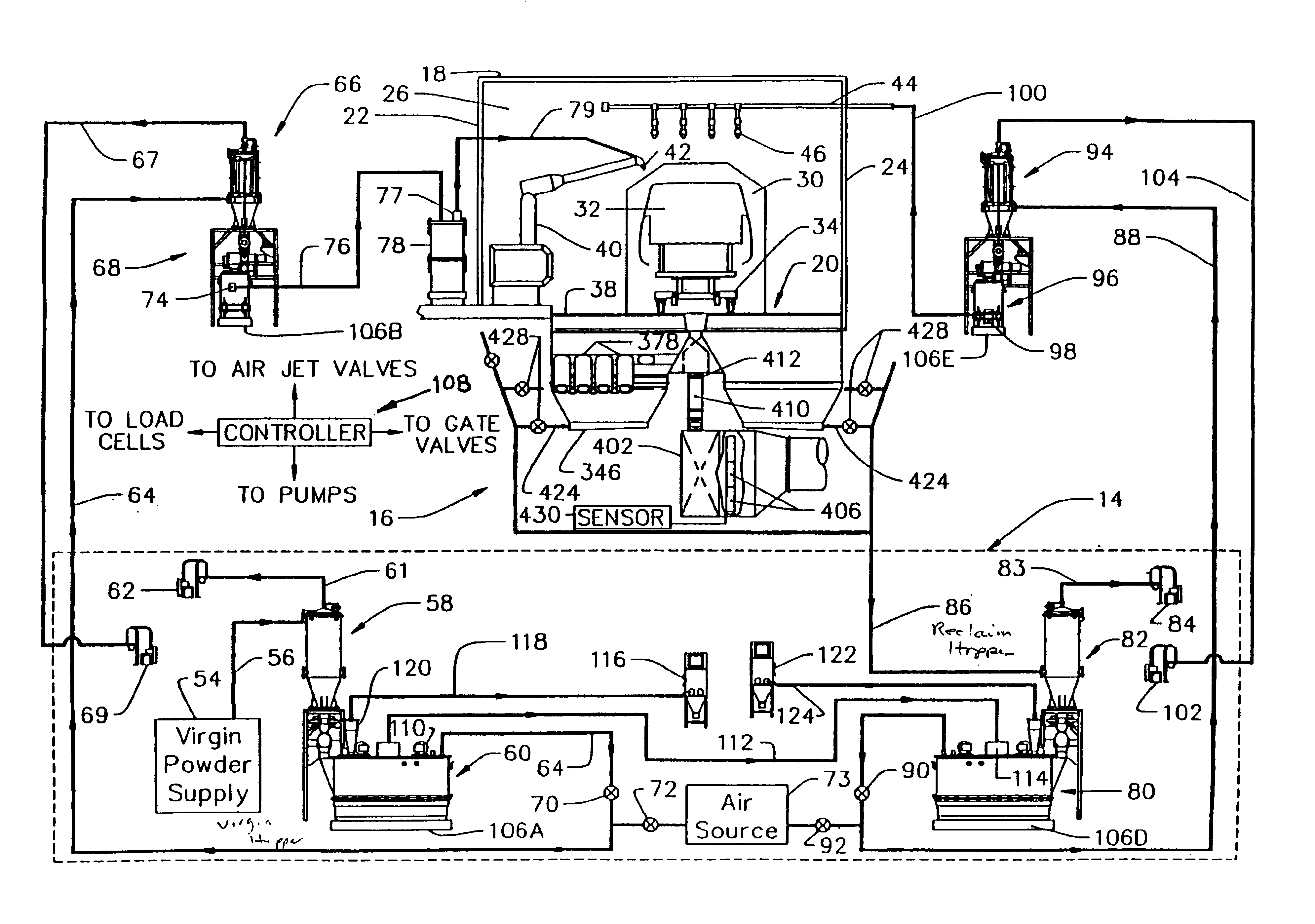
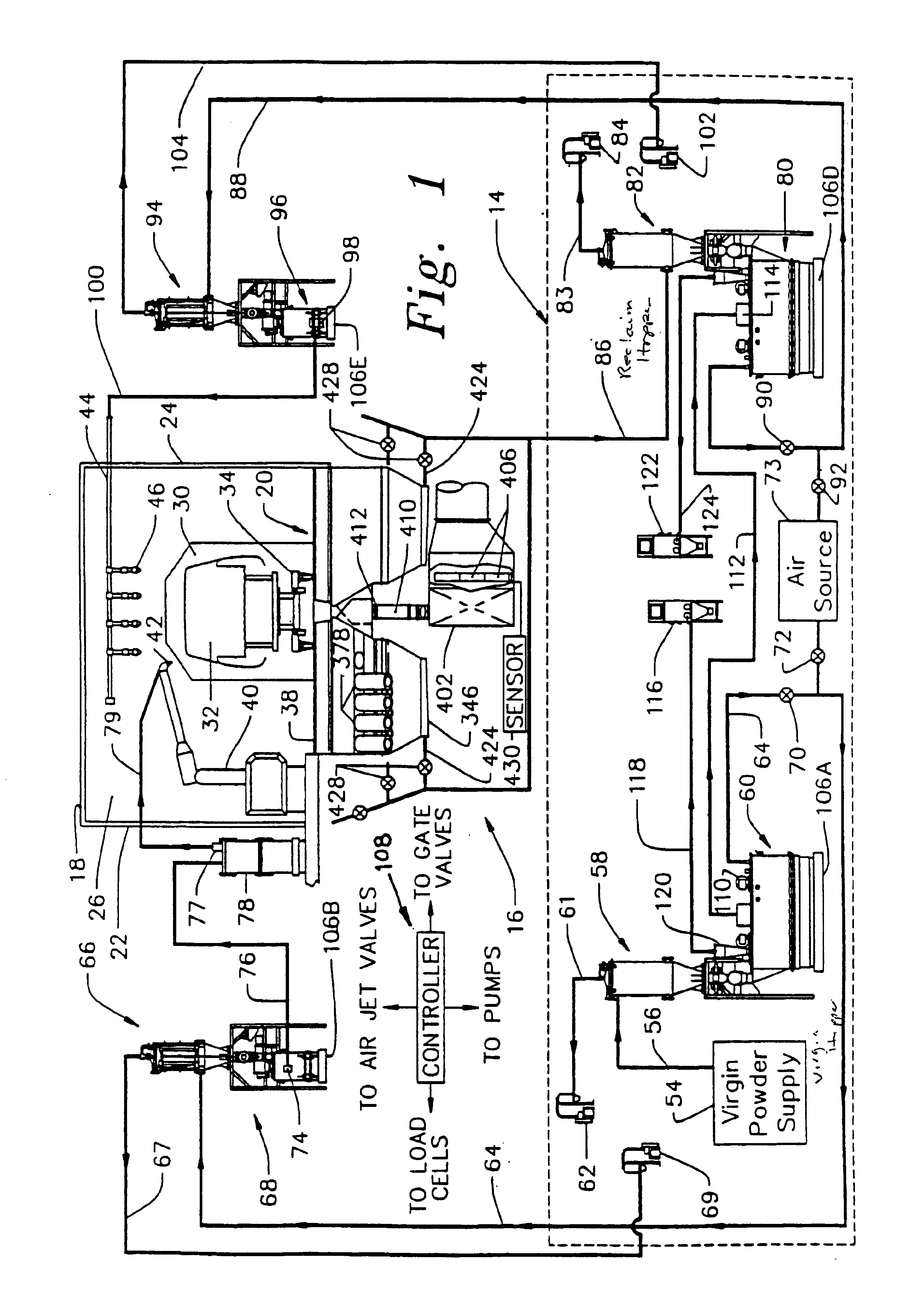
[0039]Referring now to the Figs., one embodiment of the powder coating system 10 of this invention includes a powder spray booth 12, devices for transferring powder coating material from a powder kitchen 14 to the booth 12, and, a powder collection and recovery system 16 associated with the booth 12. These system elements are described separately below, including a discussion of the operation of each.

Powder Spray Booth

[0040]Referring to FIGS. 1 and 2, the powder spray booth 12 includes a ceiling 18, floor 20, opposed side walls 22, 24 and opposed end walls defining a booth inlet 26 and a booth outlet 28. See also FIG. 7. This construction of spray booth 12 defines an interior 30 forming a controlled area in which to apply powder coating material onto objects such as a vehicle body 32 moved by a conveyor 34 through the longitudinally extending center portion 36 of the spray booth 12. Oversprayed powder material which does not adhere to the vehicle body 32 passes through gratings 38 l...


PUM


Abstract

An apparatus for applying powder coating material onto large objects such as automotive, truck or other vehicle bodies includes a powder spray booth defining a controlled area within which to apply powder coating material onto the vehicle bodies, a powder kitchen located at a remote position from the powder spray booth, and, a number of feed hoppers located proximate the booth which receive powder coating material from the powder kitchen and supply it to automatically or manually manipulated powder spray guns associated with the booth. Oversprayed powder coating material is removed from the booth interior by a powder collection and recovery system which transmits the oversprayed powder back to the powder kitchen for recirculation to the powder spray guns.

Description

[0001]This is a continuation of U.S. patent application Ser. No. 10 / 041,201 filed Jan. 8, 2002 for VEHICLE POWDER COATING SYSTEM, now U.S. Pat. No. 6,679,193 which is a continuation-in-part of U.S. patent application Ser. No. 08 / 066,873 filed May 25, 1993 now abandoned for VEHICLE POWDER COATING SYSTEM, the entire disclosures of which are hereby incorporated by reference.FIELD OF THE INVENTION[0002]This invention relates to powder coating systems, and, more particularly, to a powder coating system for use in vehicle manufacturing facilities including a powder spray booth, a powder collection and recovery system, and a powder supply which transmits virgin powder coating material and a mixture of virgin and reclaimed, or oversprayed powder coating material from a remote location to coating dispensers associated with the spray booth.BACKGROUND OF THE INVENTION[0003]The application of coating materials to large objects such as automotive and other vehicle bodies has conventionally been ...

Claims


Application Information

Patent Timeline
IPC IPC(8): B05B15/12B05B7/14B05B15/00B65G53/38B05B7/00B05B12/08B05B12/14B05C5/00B05D1/12
CPCB05B7/1404B05B7/144B05B7/1454B05B7/1468B05B7/1472B05B12/08B05B15/003B05B15/1248B05B15/1251B05B15/1229B05B12/081B05B14/48B05B14/435B05B14/43B05B15/25Y02P70/10
Inventor SHUTIC, JEFFREY R.CARLSON, JOHN F.HOLLSTEIN, THOMAS E.WILLIAMS, KEITH E.FENA, ERNEST J.LADER, HARRY J.
Owner ABB INC
Why Eureka
Try Eureka