Pneumatic tire

a technology of pneumatic tires and tyres, which is applied in the field of pneumatic tires, can solve the problems of heavy load applied to the bead portions, and reducing the durability of tires, so as to achieve the effect of reducing the proportion of low heat generating rubber used in tires, reducing the loss of tangent, and reducing the amount of rubber used

Active Publication Date: 2017-08-03
SUMITOMO RUBBER IND LTD
View PDF12 Cites 1 Cited by
  • Summary
  • Abstract
  • Description
  • Claims
  • Application Information

AI Technical Summary

Benefits of technology

[0010]The inventors have examined in detail a structure of the sidewalls each of which includes: the inner layer having a low loss tangent; and the outer layer having a loss tangent higher than the inner layer. As a result, it has been found that, even if the inner layer is extended to the bead portion, in a case where an interfacial position between the outer layer of the sidewall and the chafer is appropriately adjusted, durability can be advantageously maintained.
[0011]In the tire according to the present invention, the sidewalls each include the inner layer and the outer layer. The loss tangent of the inner layer is less than the loss tangent of the outer layer. The inner layer is formed of low heat generating rubber. When Hr represents the height, in the radial direction, from the bead base line to the outer side end of the rim, and Hi represents the height, in the radial direction, from the bead base line to the inner side end of the inner layer, the ratio (Hi / Hr) of the height Hi to the height Hr is greater than or equal to 0.0 and not greater than 3.0. The inner layer is extended to the bead portion. In the tire, the proportion of the low heat generating rubber used for the tire is greater than that for conventional tires. In the tire, rolling resistance is reduced.
[0012]The complex elastic modulus of the inner layer is less than the complex elastic modulus of the chafers. The inner layer is flexible. In the tire, a position of the inner side end Po of the interface between the outer layer and the chafer is equal to a position of the outer side end of the rim or is outward of the position of the outer side end of the rim in the radial direction. A position of the inner side end Po is equal to a position of the outer side end of the turned-up portion of the carcass ply or is inward of the position of the outer side end of the turned-up portion in the radial direction. In this structure, even if the flexible inner layer is extended to the bead portion, strain in the interface between the outer layer and the chafer is reduced. In the tire, durability is advantageously maintained in the bead portions. The tire is excellent in durability.

Problems solved by technology

Energy loss caused by the deformation and restoration is a main cause of rolling resistance of the tire.
However, heavy load is applied to the bead portions from a rim.
This may cause reduction of durability in the portions.
This may cause reduction of durability of the tire.

Method used


Image

  • Pneumatic tire
  • Pneumatic tire
  • Pneumatic tire

Examples


example 1

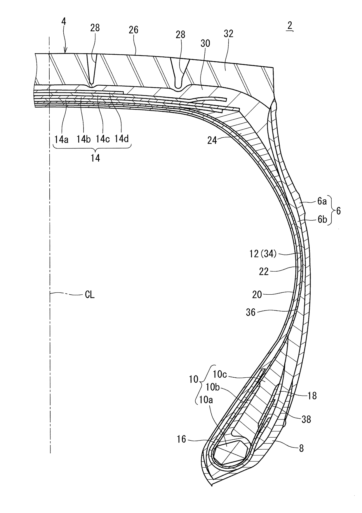
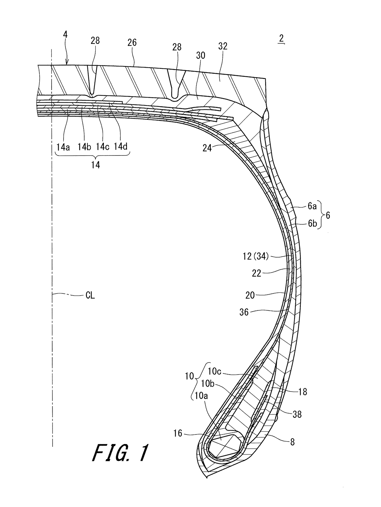
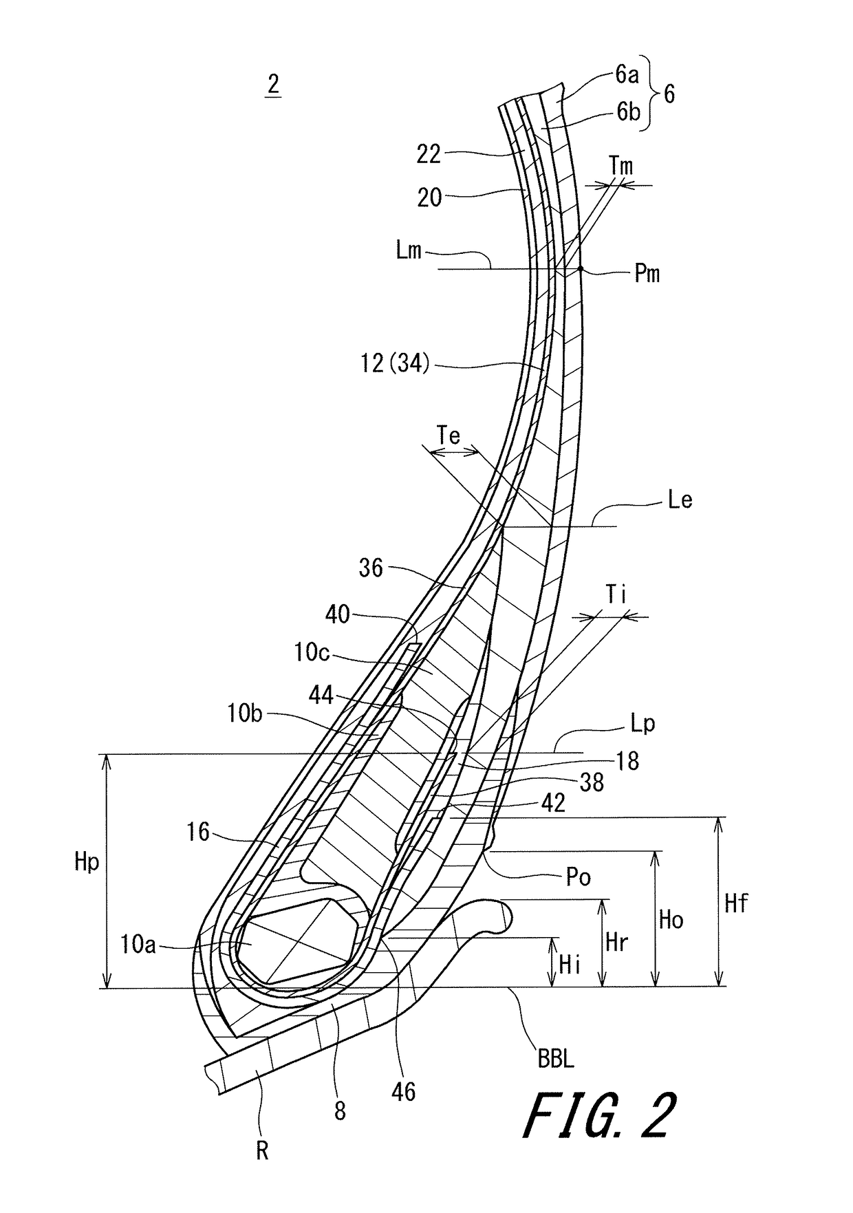
[0072]A tire, of Example 1, having the structure shown in FIG. 1 was obtained. The size of the tire was 11R22.5. Specifications of the tire are indicated in Table 1. In the tire, the thickness Te was 4.0 mm, and the thickness Tm was 3.0 mm, which are not indicated in the table. The height Hr of a flange of a rim on which the tire was to be mounted was 12.7 mm.

example 2

[0074]A tire of Example 2 was obtained in the same manner as for Example 1 except that the height Hp was different and the ratio (Hp / Hr) was as indicated in Table 1.

examples 9 to 14

[0077]Tires of Examples 9 to 14 were each obtained in the same manner as for Example 1 except that the thickness Ti was as indicated in Table 4.


PUM


Abstract

In a tire 2 of the present invention, sidewalls 6 each include an outer layer 6a, and an inner layer 6b disposed inward of the outer layer 6a in the axial direction. A loss tangent of the inner layer 6b is less than a loss tangent of the outer layer 6a. When Hr represents a height, in the radial direction, from a bead base line BBL to an outer side end of a rim R, and Hi represents a height, in the radial direction, from the bead base line BBL to an inner side end 46 of the inner layer 6b, a ratio (Hi / Hr) of the height Hi to the height Hr is greater than or equal to 0.0 and not greater than 3.0.

Description

[0001]This application claims priority on Patent Application No. 2016-018040 filed in JAPAN on Feb. 2, 2016. The entire contents of this Japanese Patent Application are hereby incorporated by reference.BACKGROUND OF THE INVENTION[0002]Field of the Invention[0003]The present invention relates to pneumatic tires. More specifically, the present invention relates to heavy duty pneumatic tires which are to be mounted to vehicles such as trucks, buses, and the like.[0004]Description of the Related Art[0005]In recent years, reduction of fuel consumption is particularly strongly required for vehicles in consideration of the environment. Tires exert influence on fuel efficiency of vehicles. Therefore, development of a “fuel-efficient tire” that contributes to reduction of fuel consumption is advanced. In order to achieve, by a tire, reduction of fuel consumption, it is important to reduce rolling resistance of the tire. When a tire rolls, deformation and restoration are repeated. Energy loss...

Claims


Application Information

Patent Timeline
Patent Type & Authority Applications(United States)
IPC IPC(8): B60C13/00B60C15/00B60C15/06
CPCB60C13/00B60C15/06B60C15/0027B60C2200/06B60C2013/007B60C2015/0614B60C2013/006B60C15/0628B60C15/0653B60C13/04B60C3/04B60C2013/045
Inventor TODOROKI, DAISUKE
Owner SUMITOMO RUBBER IND LTD
Why Eureka
Try Eureka