Eureka AIR delivers breakthrough ideas for toughest innovation challenges, trusted by R&D personnel around the world.

Dental imager and method for recording photographic impressions

a dental impression and imager technology, applied in the field of dental impression recording, can solve the problems of limiting the ability of patients to breathe properly, limiting the ability of patients to rest properly, and presenting numerous limitations and inconveniences in the recording form of dental impressions, so as to improve image quality and reduce errors

Active Publication Date: 2017-08-03
MARTIN MARCO
View PDF7 Cites 23 Cited by
  • Summary
  • Abstract
  • Description
  • Claims
  • Application Information

AI Technical Summary

Benefits of technology

The dental imager described in this patent has various features to improve image quality and make the dental imaging process easier for dental professionals. It includes an elongated handle with a rubber grip, a head with a size and shape for insertion into the intraoral cavity, and at least one lateral scanning arm with a scanner for imaging the teeth. A guide is provided to position the scanner at a preferred location relative to the teeth and gums as the dental imager moves. The dental imager may also include a front and rear medial scanning arm to enhance scanning coverage. The guide may include a front pad and a rear pad for better positioning of the scanners during scanning. Overall, the dental imager improves dental imaging by providing better access and positioning of the scanners, resulting in higher quality images.

Problems solved by technology

This form of recording dental impressions presents numerous limitations and inconveniences.
The solidification process may be an uncomfortable experience for patients who remain in a reclined position with their mouth open for a prolonged period of time (e.g., six to ten minutes).
Moreover, the chemical paste generates excessive salivation during the impression curing process, which can limit the ability of the patient to breathe properly, especially when reclined.
The removal of the cured dental impression can also be an uncomfortable experience for the patient, even when done properly.
Discomfort is compounded by the fact that chemical pastes used to create the dental impression may leave a bad taste in the mouth, even after removal, as residues of the paste get stuck in the cracks of the teeth.
Moreover, the physical impression is typically unable to capture every indentation, crack, or protuberance of the oral cavity.
For example, if the patient has attachments on the surface of their teeth, including braces or permanent retainers, the entire process is compromised and it may not be possible to create a physical dental impression.
This is because the attachments unavoidably jeopardize the accuracy and integrity of the impression during the curing and removal steps.
Moreover, the inability to prevent scratching of the cured chemical paste mold sometimes results in the undesirable need to re-take the dental impressions (i.e., re-do the mold).
The nature, consistency, and malleability of physical dental impression bodies also make taking a targeted impression of only a limited area within the oral cavity extremely difficult, if not impossible.
Creating dental impressions with an impression and mold also creates excessive waste from both the impression curing process and the creation of the durable resulting mold.
Creating physical dental impressions may also be time consuming and labor intensive.
Inadequately trained and especially inexperienced personnel inevitably need to take multiple dental impressions of the same patient in one sitting, until a proper mold has been generated.
This is undesirable for the patient and practitioner.
In this respect, some systems are designed to mimic the “U”-shape dental trays in the form of a scanner, but those too include limitations regarding the wide scanning area and the amount of data gathered.
Moreover, the “U”-shaped dental scanners are also unable to efficiently take an impression of a single tooth or selected area of the mouth given that the “U”-shaped tray necessitates scanning the entire dental arc, thereby inherently including the same limitations as current methods related to “U”-shaped trays that utilize chemical paste.
While these systems may be designed to replace curing chemical pastes with digital scanners, such systems are not necessarily significantly more efficient.
Although, illumination and recordation of translucent oral objects does not allow for readily-available surface mapping, as the light passes through the object before being recorded, rather than bouncing off the object.
Consequently, it is not possible to image completely opaque objects.
Although, without proper guides, it is difficult to achieve the correct shape and distances being scanned.
Moreover, such a wand increases the potential for accidental scans of the tongue and other parts of the mouth, thereby decreasing the accuracy of the scans and / or requiring user training to ensure an accurate the 3D model is produced.
Despite addressing some of the problems associated with physical dental impression molds, known digital impression systems include drawbacks.
For example, “U”-shaped scanner arrays and “U”-shaped tracks with movable scanners are limited by size and are not always able to fit every oral cavity size.
This can present an issue, for example, when trying to scan the mouth of a child when using a device sized to scan an adult mouth.
This means a large initial expense for equipment, thus inhibiting the potential cost advantage of foregoing the consumables needed to create physical dental impression bodies and molds.
The unconstrained nature of current hand-held scanning systems may require additional training so the practitioner understands how to obtain accurate images since a guide is notably absent.
These limitations can result in digital representations of the oral cavity that need correction or post-processing before being usable, thereby increasing time and cost for producing a dental impression.

Method used


Image

  • Dental imager and method for recording photographic impressions
  • Dental imager and method for recording photographic impressions
  • Dental imager and method for recording photographic impressions

Examples


Embodiment Construction

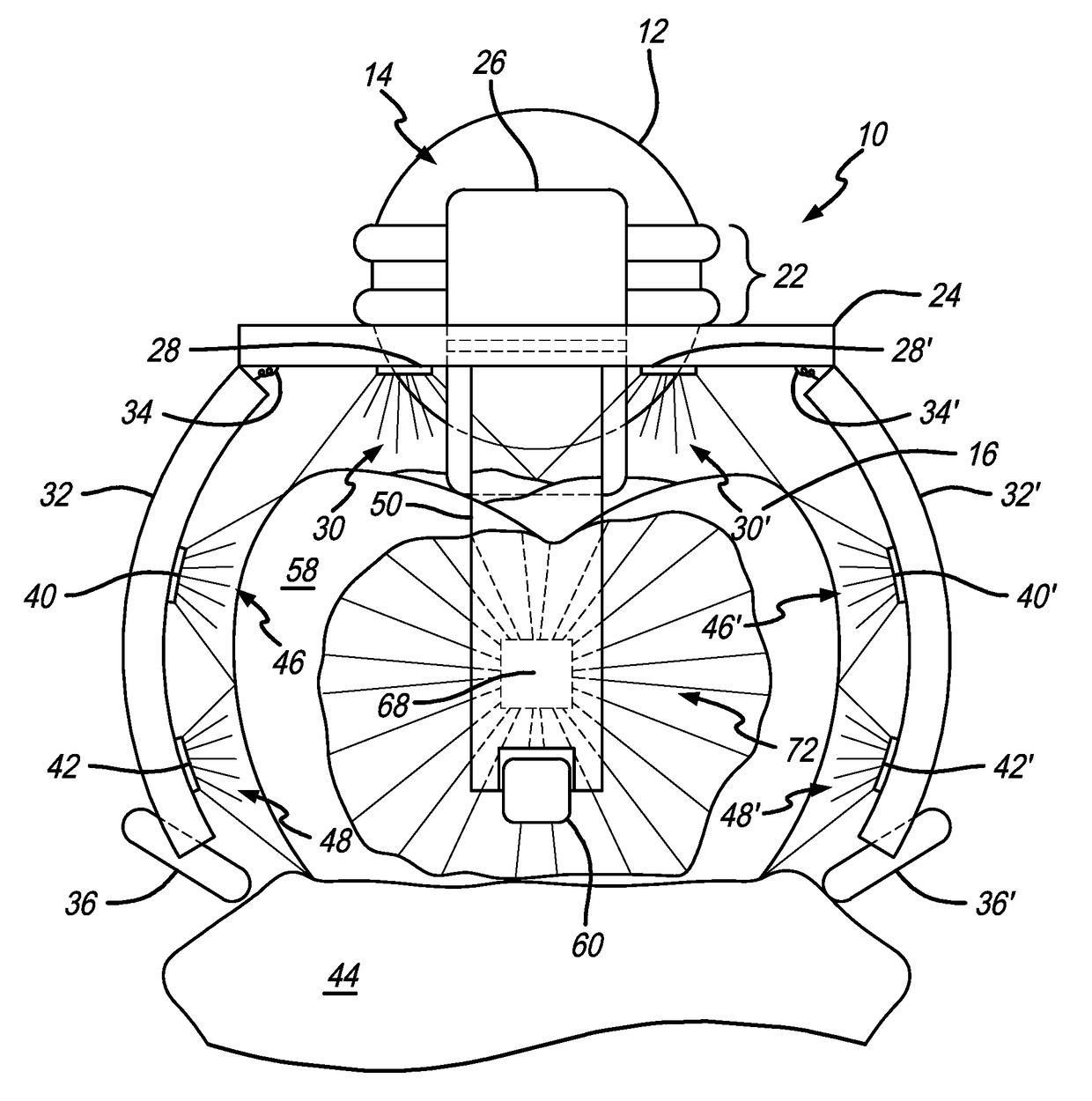
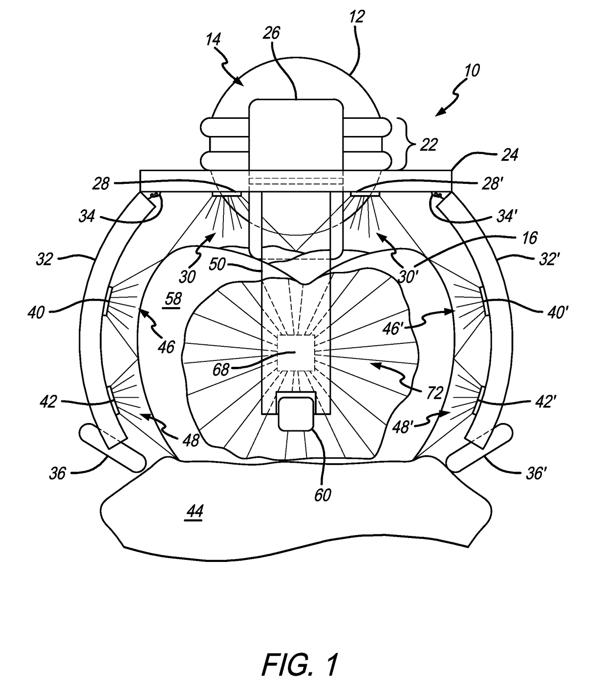
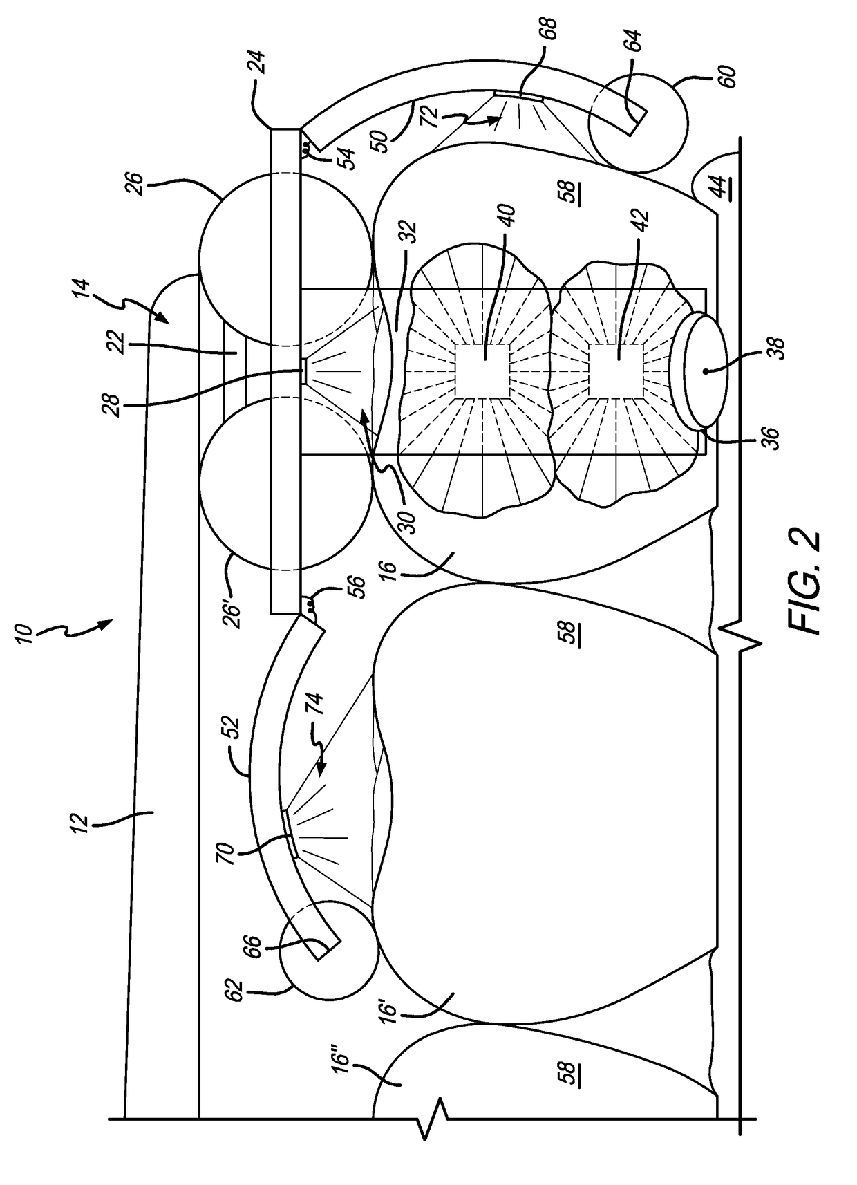
[0051]As shown in the exemplary drawings for purposes of illustration, embodiments for a dental imager as disclosed herein are generally referred to by reference numeral 10 in FIGS. 1-3 and 5-11. In general, the dental imager 10 is a relatively simple design that facilitates quick learning and a “one size fits all” solution, thereby reducing the time to train personnel to take accurate dental impressions, and may be used to image, scan, examine, and / or map the three-dimensional characteristics of intraoral surfaces, such as teeth. For instance, the dental imager 10 can be used to capture the exact shape of a single tooth, multiple teeth in one or more locations, a portion of a dental arc, or the entire dental arc for faster diagnosis. The dental imager 10 also eliminates the inaccuracies of creating dental impressions when a scanned surface is uneven (e.g., teeth surrounded by braces or other dental fixtures) and can provide still images or real-time video output to a viewing monito...


PUM


Abstract

A dental imager includes an elongated handle with a rotatable head coupled to a distal end thereof and having a central platform with a plurality of arcuate scanning arms pivotally coupled thereto by a hinge. The arcuate scanning arms are of a shape and size for general deployment around a tooth and each include at least one scanner and a roller guide that comfortably rolls along the surface of the tooth or gums to bias the scanners a desired distance from the surface of the tooth, conducive for imaging thereof. In this respect, such a dental imager may be used in a process to scan and record the contours of an intraoral surface, the data of which may be used to create a digital three-dimensional surface impression printable by a 3D printer or the like.

Description

BACKGROUND OF THE INVENTION[0001]The present invention generally relates to a dental imager and related method for collecting digital impressions. More specifically, the present invention relates to a dental imager in the form of a hand-manipulatable scanner that digitally records three-dimensional images of the contours and surfaces of the oral cavity when biased away and passed over teeth.[0002]A dental impression is a reproduction of an oral cavity. Dentists, orthodontists, and dental practitioners collect dental impressions for a variety of reasons, such as making removable dentures, making and installing dental crowns, creating a dental bridge, repairing installed dentures, making a mouth guard or customized enamel whitening tray, creating models for diagnostic study, or manufacturing and installing other oral appliances, etc.[0003]Currently, trained practitioners can take dental impressions by creating a solid mold of the oral cavity. The process requires filling a “U” shaped ...

Claims


Application Information

Patent Timeline
Patent Type & Authority Applications(United States)
IPC IPC(8): A61C9/00A61B1/00A61B1/06A61B1/24
CPCA61C9/008A61B1/24A61C9/0053A61B1/00013A61C9/0086A61B1/00018A61B1/063A61B1/0684A61B1/00101A61B1/00016A61B1/00172A61B1/247A61B5/1079A61B5/0062A61B5/0088A61B5/1077A61B1/00148A61B1/00194A61B5/6835A61B5/682A61B5/45A61B5/4542A61B1/05A61B5/6844A61B5/4547A61B90/50A61B1/00149A61B2560/0406A61B5/14542A61B6/51
Inventor MARTIN, MARCO
Owner MARTIN MARCO
Why Eureka
Eureka Blog
Learn More