
Mesoscopic framework for organic-inorganic perovskite based photoelectric conversion device and method for manufacturing the same

Active Publication Date: 2017-07-27
ECOLE POLYTECHNIQUE FEDERALE DE LAUSANNE (EPFL) +1
View PDF1 Cites 12 Cited by
  • Summary
  • Abstract
  • Description
  • Claims
  • Application Information

AI Technical Summary

Benefits of technology

The present invention aims to improve the preparation of perovskite solar cells and provide a more convenient way of using it for high power conversion efficiency. The goal is to solve the problems of high cost and difficulty in preparing perovskite solar cells.

Problems solved by technology

With the large consumption of traditional fossil energy sources, environmental pollution is worsening and the global energy crisis has become increasingly prominent.
But the purity of the silicon solar cell materials, the demand for crystal, complex process of fabrication, high production costs are drawbacks to incite the development of low-cost and simple preparation fabrication process of new solar cell and to obtain a solar cell with large scale application.
Because a solar cell uses solar energy, being an infinite and environmental-friendly energy source, unlike other energy sources, the solar cell has been in the spotlight due to an energy shortage problem.
Since a Si solar cell was developed in 1983; implementing silicon for photovoltaic cells generally requires high product cost due to extensive material and energy consumption.
However, these thin film PV cells generally require a high vacuum manufacturing process, which generally leads to high capital investment and operational expenses.
When organic materials are used, these organic materials are more expensive and the application costs increase.
Because the long-term properties of these organic materials are difficult to maintain, subsequent packaging process of battery device and long-term stability of device applications represent a challenge.
The film quality and thickness of a metal oxide of the hole transport layer, and the presence of impurities, defects and pinholes within the film will seriously affect the photoelectric conversion efficiency of solar cells.
These controls also increase the manufacturing costs of the solar cell.
Further, mesoporous structure in the perovskite hole transport layer solar cells has not yet been reported.
However, manufacturing the hole-transportation organic materials (such as spiro-OMeTAD) commonly used in solid-state DSSC or perovskite solar cell is very costly and lack long term stability.
However, inorganic HTMs are uncommon in this class of devices as a hole transport layer for very poor performance, and thus there has been a need for improvement from these aspects.

Method used


Image

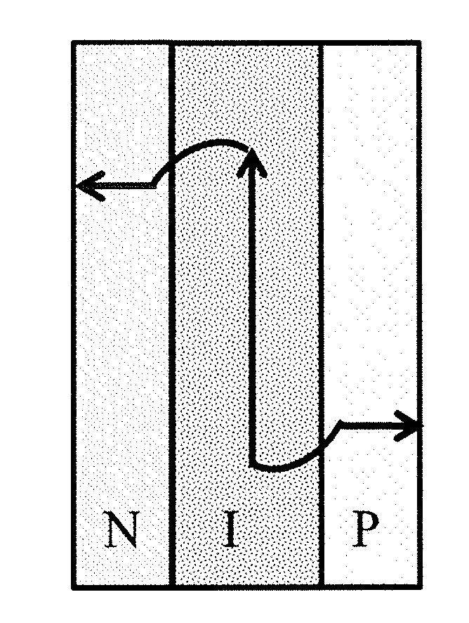
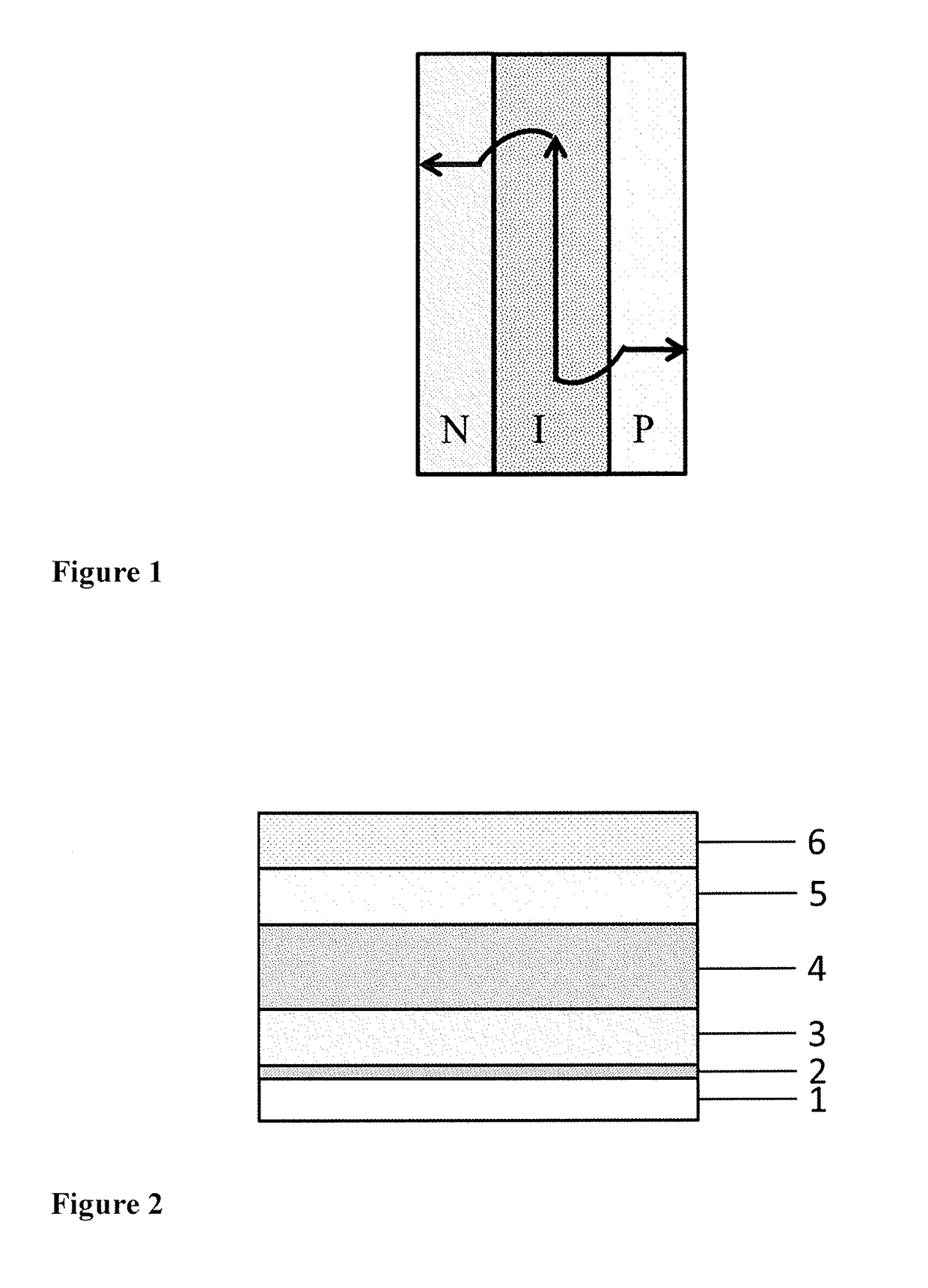
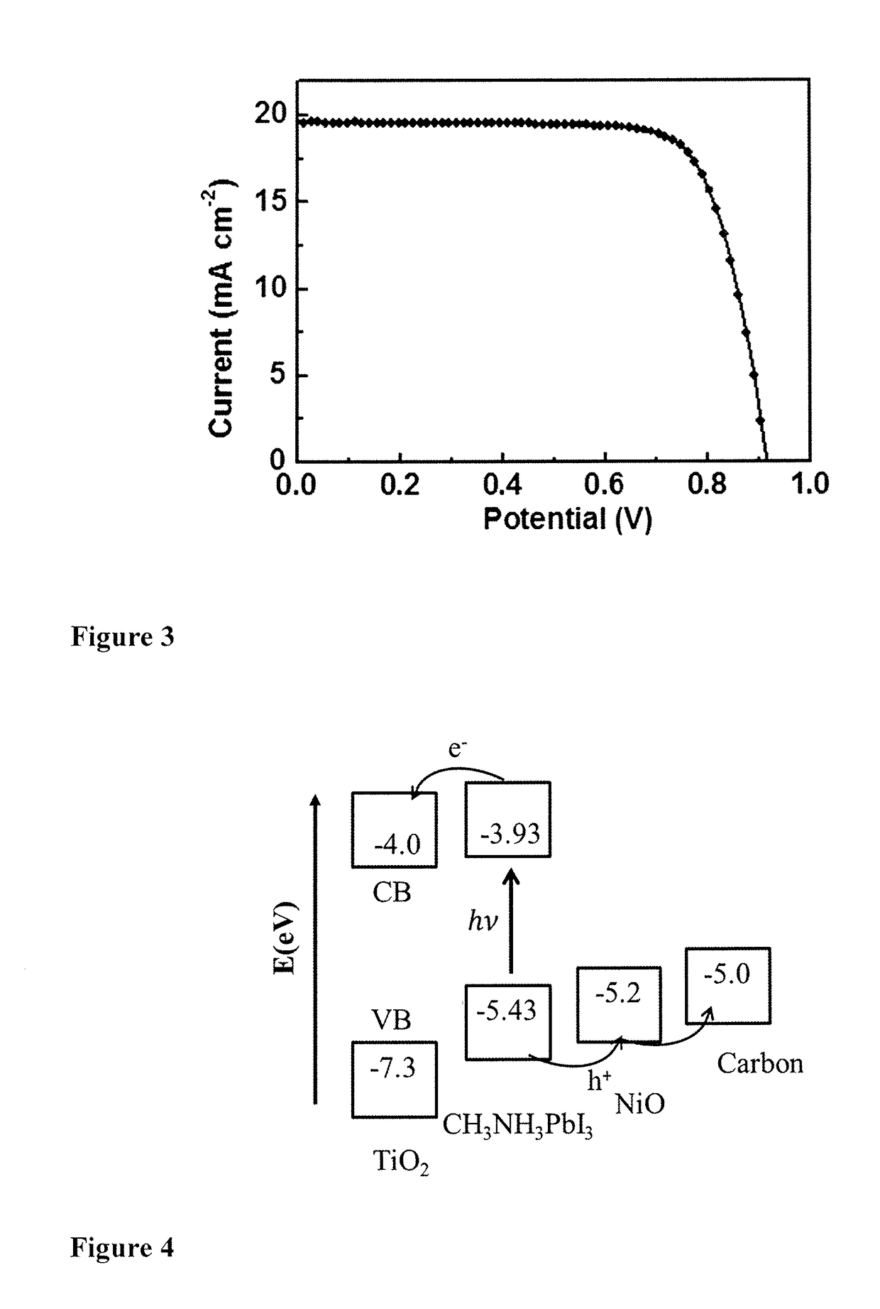
  • Mesoscopic framework for organic-inorganic perovskite based photoelectric conversion device and method for manufacturing the same
  • Mesoscopic framework for organic-inorganic perovskite based photoelectric conversion device and method for manufacturing the same
  • Mesoscopic framework for organic-inorganic perovskite based photoelectric conversion device and method for manufacturing the same

Examples


example 1

[0100]Preparation of a Mesoporous Inorganic P-I-N Metal Oxides Framework

[0101]The substrate of the device was a glass substrate covered with fluorine-doped tin oxide (FTO), wherein the thickness of the glass substrate was 4 mm and the electric resistance of the glass substrate is 10 Ω. A blocking layer of TiO2 was deposited on the FTO glass by spray pyrolysis deposition with di-isopropoxytitanium bis(acetyl acetonate) (TiDIP, 75% in isopropanol, Aldrich) solution at 450° C. A mesoporous inorganic N-type semiconductor layer was coated by screen printing method using a paste containing TiO2 particles with diameter of 20 nm (DSL. 18NR-T, 20 nm, Dyesol, Austrilia) for one time or several times. The thickness of the TiO2 layer was 400 nm, and then dried in 125° C. for 10 min. Then, a mesoporous inorganic insulating layer was coated by the same screen printing method using a paste containing Al2O3 particles with diameter of 20 nm (Aladdin, 20 nm, China). The thickness of the TiO2 layer wa...

example 2

[0102]Preparation of a Mesoporous Inorganic P-I-N Metal Oxides Framework

[0103]The process for preparing the mesoporous inorganic P-I-N metal oxides framework of the present embodiment was the same as that described in Example 1, except that the TiO2 particles was substituted with the ZnO particles with diameter of 10 nm and the thickness of ZnO layer was 200 nm. Then, the coated glass substrate was sintered at 500° C. for 30 min, and the thickness of the mesoporous inorganic P-I-N metal oxides framework was 1.2 μm.

example 3

[0104]Preparation of a Mesoporous Inorganic P-I-N Metal Oxides Framework

[0105]The process for preparing the mesoporous inorganic P-I-N metal oxides framework of the present embodiment was the same as that described in Example 1, except that the Al2O3 particles was substituted with the ZrO2 particles with diameter of 50 nm and the thickness of ZrO2 layer was 600 nm. Then, the coated glass substrate was sintered at 500° C. for 30 min, and the thickness of the mesoporous inorganic P-I-N metal oxides framework was 1.6 μm.


PUM


Abstract

The invention discloses a perovskite solar cell and a method of fabrication thereof. The perovskite solar cell sequentially comprises a transparent electrode, a mesoporous P-I-N framework and a counter electrode from the bottom to top; the mesoporous P-I-N framework is composed of an n-type semiconductor layer, an insulating layer, and a p-type semiconductor layer in a sequentially stacked mode, and the n-type semiconductor layer, the insulating layer and the p-type semiconductor layer all comprise mesopores filled with a perovskite material. The preparation method sequentially includes preparing the mesoporous P-I-N framework on a transparent conductive substrate through a spin-coating method or a screen printing method, filling with the perovskite material and preparing the counter electrode layer.

Description

TECHNICAL FIELD[0001]This invention generally relates to methods for producing photoelectric conversion devices, and more specifically, to a method for producing organic-inorganic perovskite based photoelectric conversion devices having designed mesoscopic framework using inorganic semiconductor layers.PRIOR ART AND THE PROBLEM UNDERLYING THE INVENTION[0002]Nowadays, in order to solve a facing energy problem, various researches for energy that can replace existing fossil fuels have been progressed. Energy is the driving force of the development and progress of human society being important basis for national economic development and the improvement of people's living standards. With the large consumption of traditional fossil energy sources, environmental pollution is worsening and the global energy crisis has become increasingly prominent.[0003]Solar cells converting solar energy directly into electricity are the solution to the global energy crisis and represent one important way ...

Claims


Application Information

Patent Timeline
IPC IPC(8): H01G9/20H01L51/44H01G9/00H01L51/42
CPCH01G9/2018H01L2251/301H01L51/4226H01L51/4233H01L51/422H01L51/442H01L51/447H01G9/2027H01G9/2022H01G9/209H01G9/0036H01L2251/308H01L2251/306H01L2251/305H01L51/4293H10K71/13H10K30/10H10K2102/00Y02E10/549Y02E10/542Y02P70/50H10K85/00H10K30/152H10K30/15H10K30/151H10K30/40H10K2102/101H10K2102/102H10K2102/103H10K85/50H10K30/82H10K30/87
Inventor WANG, MINGKUICAO, KUNCUI, JINZUO, ZHIXIANGSHEN, YANZAKEERUDDIN, SHAIK MOHAMMADGRAETZEL, MICHAEL
Owner ECOLE POLYTECHNIQUE FEDERALE DE LAUSANNE (EPFL)
Learn More