Measurement technique for thin-film characterization

a thin film and measurement technique technology, applied in the field of measurement techniques for characterizing thin films, can solve the problems of time-consuming and inefficient, destroying the thin film sample to be measured, and it is difficult to characterize the hall coefficient of the sample and its mobility with any accuracy, and achieves low microwave loss tangent and high permittivity.

Active Publication Date: 2017-07-27
NPL MANAGEMENT
View PDF2 Cites 7 Cited by
  • Summary
  • Abstract
  • Description
  • Claims
  • Application Information

AI Technical Summary

Benefits of technology

[0023]Preferably, the resonator is made of a material selected from the group consisting of sapphire (Al2O3), lanthanum aluminate (LaAlO3), rutile (TiO2), strontium titanate (SrTiO3) and magnesium oxide (MgO), which are all materials having a high permittivity and a low microwave loss tangent, when grown as a single crystal. Preferably, the relative permittivity of the resonator is greater than 8 and the microwave loss tangent of the resonator is less than 10−4.
[0024]It is also preferred that the electric field excited in the resonator should be a TEnmp mode with n>0. Of these, a TE110 mode is preferred, although higher order modes may also be used.
[0025]The comparator circuit may comprise a vector network analyser (VNA) with channels respectively connected to the first one of the plurality of ports used to inject microwaves into the resonance chamber and to another of the plurality of ports used to receive microwaves from the resonance chamber. This allows either the conductivity or sheet resistance or the carrier mobility of a thin film sample to be derived in the frequency domain. In an alternative embodiment, the comparator circuit may include a loop oscillator comprising a fast microwave switch connected to one of the plurality of ports used to receive microwaves from the resonance chamber, a phase shifter connected to the fast microwave switch, a tunable band pass filter connected to the phase shifter, and a microwave amplifier connected to the band pass filter and to the first one of the plurality of ports used to inject microwaves into the resonance chamber. This allows either the conductivity or sheet resistance or the carrier mobility of a thin film sample to be derived in the time domain.

Problems solved by technology

Such techniques can exhibit the disadvantages of being time-consuming and inefficient to prepare the samples as Hall bar devices and destructive of the thin-film sample to be measured.
However, this technique has the disadvantage that although the sample is not destroyed by such a technique, it is difficult to characterize the Hall coefficient of the sample and its mobility with any accuracy.
Firstly, it is difficult to achieve a high Q-factor in the cavity.
Secondly, only samples of very small volume can be used and usually the shape and position of the sample within the cavity are critical, since the complicated geometry of the rectangular cavity relative to the sample makes calculation of the coupling between the sample and the cavity problematic.

Method used


Image

  • Measurement technique for thin-film characterization
  • Measurement technique for thin-film characterization
  • Measurement technique for thin-film characterization

Examples


Embodiment Construction

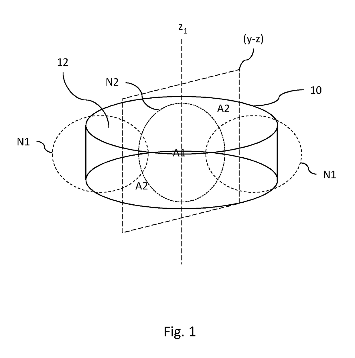
[0043]Referring firstly to FIG. 1, there is shown a dielectric resonator 10 having a top surface 12. In this embodiment, the dielectric resonator 10 is in the shape of a right circular cylinder of rotation about a first symmetry axis, z1, although in alternative embodiments, it could be other shapes, such as a right prism having a square or rectangular top surface, provided that the resonator always has at least a first symmetry axis, z1. The resonator 10 is made of a single crystal of a high permittivity material with a low microwave loss tangent, such as sapphire, which has a relative permittivity of 11.6 on its a crystallographic axis and of 9.4 in its b-c crystallographic plane, and a microwave loss tangent of less than 10−5. The dielectric resonator 10 is grown so that the a crystallographic axis is aligned with the first symmetry axis, z1, of the resonator.

[0044]The dielectric resonator 10 is made with a width (or in this embodiment, a diameter) convenient to measure the carri...


PUM

PropertyMeasurementUnit
relative permittivityaaaaaaaaaa

Abstract

A measurement device comprises a high permittivity dielectric resonator (10) with a low microwave loss tangent and having at least a first symmetry axis (z-i); an electrically conductive resonance chamber (100) containing and geometrically similar to the resonator (10) and having a second symmetry axis (z2) coincident with the first symmetry axis (z-i); the resonance chamber (100) having a plurality of similar ports (104) orthogonal to the first symmetry axis (z-i), each such port (104) having a microwave antenna (114), either to inject microwaves into the resonance chamber, thereby to excite an electric field in the resonator, or to receive microwaves from the resonance chamber; and a comparator circuit (200, 300, 400, 500, 600, 700, 800) connected to a first one (P1) of the plurality of ports (104) to inject microwaves into the resonance chamber and to another (P2, P3) of the plurality of ports (104) to receive microwaves from the resonance chamber; wherein the measurement device further comprises an electrically conductive tuning screw (106) in electrical contact with the resonance chamber (100), the tuning screw being at least partially positionable in the electric field thereby excited in the resonator; and a source of magnetism (18) to apply a magnetic field to a sample brought into proximity with a top surface (12) of the resonator (10) substantially parallel or anti-parallel to the first symmetry axis (z-i); and wherein one (P3) of the other of the plurality of ports (104) to receive microwaves from the resonance chamber (100) is orthogonal to the first one (P1) of the plurality of ports (104) to inject microwaves into the resonance chamber. Such a measurement device may be used to measure both the conductivity or sheet resistance of a thin film (30), as well as the carrier mobility of the thin film, without contacting the resonator (10) with either the thin film or a substrate (20) on which the thin film is formed.

Description

FIELD OF THE INVENTION[0001]The present invention concerns measurement techniques for characterizing thin films, and in particular for determining the carrier mobility of a thin film, as well as the conductivity or equivalently, the sheet resistance of a thin film.BACKGROUND ART[0002]The inventors have previously described a technique for measuring the conductivity and sheet resistance of thin-film samples of graphite comprising monolayers and very few layers of graphene in their paper “Non-contact method for measurement of the microwave conductivity of graphene” in Applied Physics Letters, Vol. 103, pp. 123103-1-123103-4 (2013). This technique uses a high Q-factor dielectric resonator, made of a single crystal of a high permittivity material with a low microwave loss tangent, such as sapphire, which is excited by microwaves in a conducting chamber, to measure the conductivity of such thin-film samples in a non-contacting manner. As described at the end of that paper, the present in...

Claims


Application Information

Patent Timeline
Patent Type & Authority Applications(United States)
IPC IPC(8): G01N22/00
CPCG01N22/00G01N27/041H01P7/10
Inventor HAO, LINGGALLOP, JOHN CHARLES
Owner NPL MANAGEMENT
Why Eureka
Try Eureka