
Distributed Optical Fibre Sensors

a technology of optical fiber sensors and distributed optical fibres, applied in the direction of converting sensor output optically, instruments, measurement devices, etc., can solve the problems of exceeding the range limit of the interrogator, limiting the distance range of the distributed optical fibre sensor based on the optical time domain reflectometry (otdr) principle, and requiring additional interrogation systems to be provided, so as to increase the useful sensing coverage of the environment

Active Publication Date: 2017-07-20
VIAVI SOLUTIONS INC
View PDF5 Cites 41 Cited by
  • Summary
  • Abstract
  • Description
  • Claims
  • Application Information

AI Technical Summary

Benefits of technology

The present invention provides methods and apparatus for improving the useful sensing coverage of an environment by a distributed optical fibre sensor. This is achieved by permitting multiple sensing optical fibres to be interrogated concurrently, which allows for detection of acoustic signals from the parts of the environment covered by the sensor. The interrogation rate and acoustic bandwidth of the sensor are limited by the propagation delay of the backscattered light from the sensing optical fibre. The invention provides sensor apparatus that can compromise between the distance range and sensing bandwidth limitations by sending sequential interrogation pulses along different optical fibre paths that are each within the range limit of the system. The interrogator unit can generate a repeating set of optical pulses with the interval between each pulse in the sequence determined by the length of each individual sensing optical fibre within the set of fibres to be monitored.

Problems solved by technology

However, the distance range of a distributed optical fibre sensor based on optical time domain reflectometry (OTDR) principles is limited by the power budget of the system, which in turn is controlled by various factors, including the maximum permissible launched power of probe light pulses for avoidance of nonlinear optical effects in the sensing optical fibre, and the noise properties of the photo detection system.
This can lead to requirements for additional interrogation systems to be provided if more fibre length needs to be monitored in an environment.
Often, vibration monitoring is required at many physically separated points near to an interrogator, such that every point lies within the range limit of the system, but a single length of sensing optical fibre reaching all of the required locations may exceed the range limit for the interrogator because of the complex fibre path required to reach all of the locations to be monitored.
Use of a single sensor fibre to monitor all the required locations in the environment may also lead to increased vulnerability to fibre damage.

Method used


Image

  • Distributed Optical Fibre Sensors
  • Distributed Optical Fibre Sensors
  • Distributed Optical Fibre Sensors

Examples


Embodiment Construction

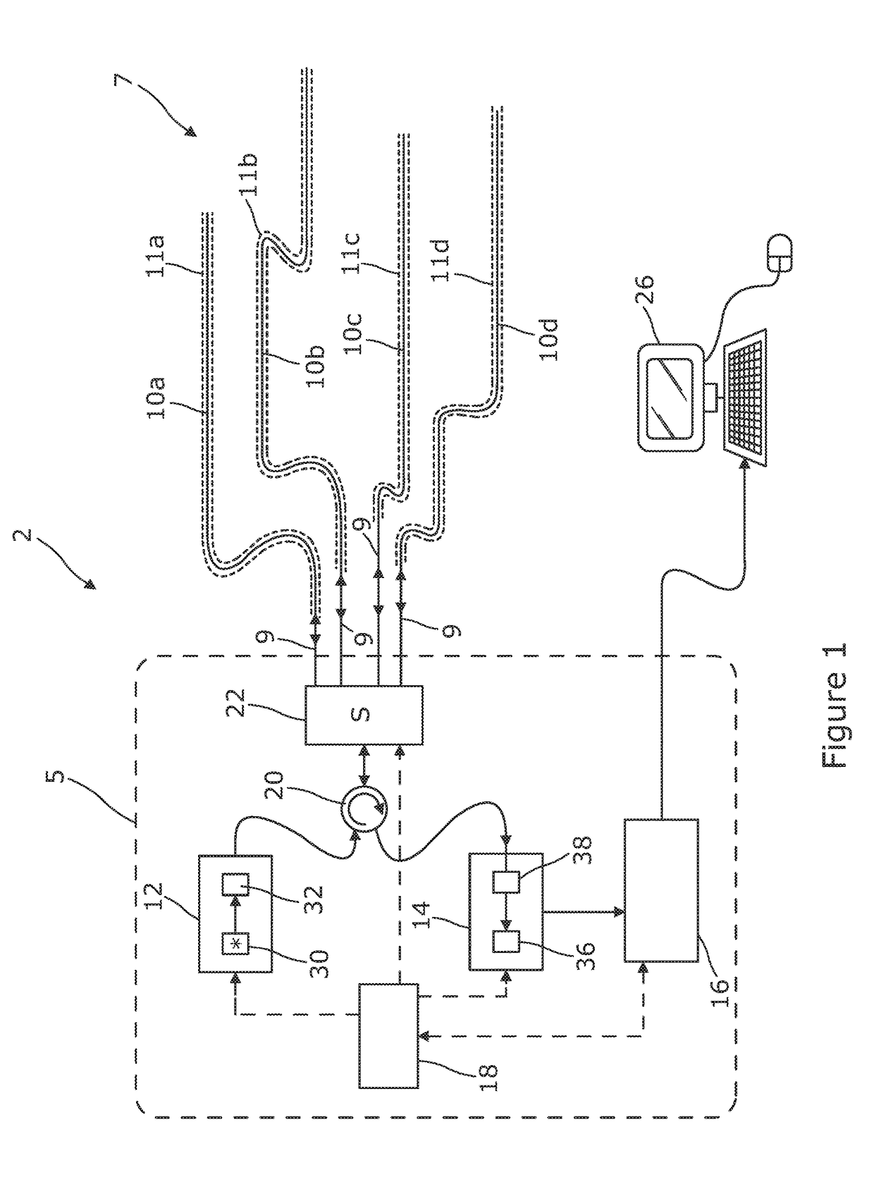
[0039]Referring to FIG. 1 there is illustrated a distributed optical fibre sensor 2 arranged to sense one or more physical parameters of an environment 7 as a function of position along part or all of each of a plurality of sensing optical fibres 10a-10d using optical time domain reflectometry (OTDR), or another reflectometry technique such as frequency domain reflectometry. An interrogator unit 5 of the sensor 2 includes a probe light source 12 for generating probe light pulses of suitable timing, shape and wavelength, a detector 14 for detecting probe light resulting from the probe light pulses being backscattered within the sensing fibres 10a-10d, and an analyser 16 for processing data, such as properties of the backscattered and detected light, which has been received from the detector 14.

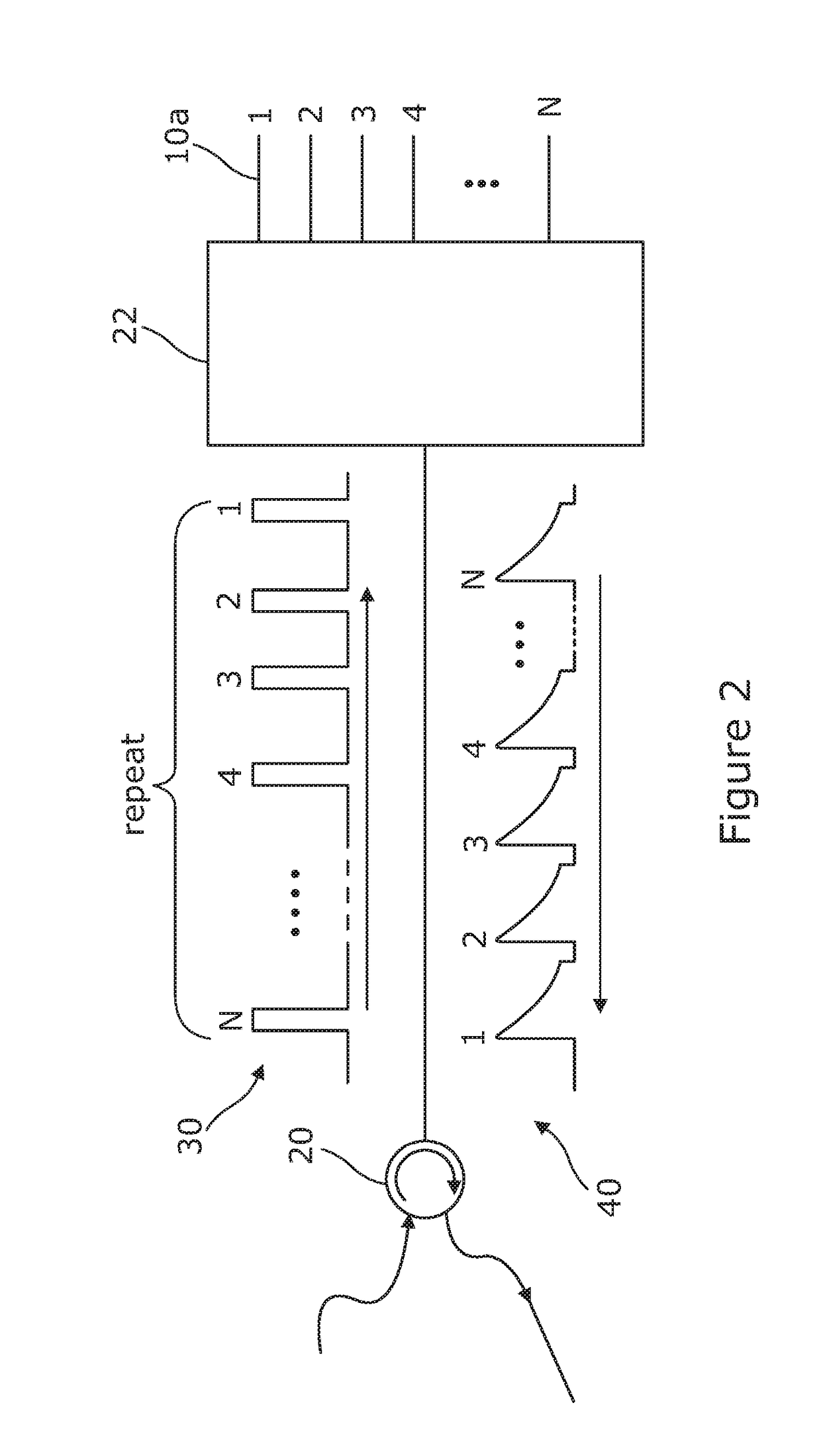
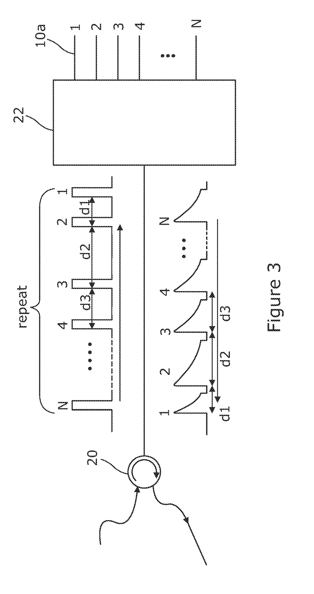
[0040]The probe light source 12 forms probe light pulses which are forwarded to an optical circulator 20 and from there on to an optical switch 22. The optical switch 22 is arranged to couple e...


PUM


Abstract

Distributed optical fibre sensor measures vibration, as a concurrent function of position along each of a plurality of sensing optical fibres, from properties of probe light backscattered within the sensing optical fibres. The sensor includes a light-pulse-generating probe light source, a detector, an optical switch. The sensor is arranged to control the optical switch such that all of the sensing optical fibres can be used concurrently to detect acoustic vibration, and an analyser is arranged to determine vibration, as a concurrent function of position along each of the sensing optical fibres, from the detected backscattered probe light.

Description

[0001]The present invention relates to sensors using multiple optical fibres. Aspects of the invention relate in particular to distributed optical fibre sensors in which one or more physical parameters are sensed as a function of position along a plurality of sensing optical fibres from properties of probe light backscattered within the sensing fibres. Such sensors may for example be optical time domain reflectometry (OTDR) sensors for use in sensing acoustic vibration, and such sensors which use phase sensitive OTDR techniques such as through the detection of coherent Rayleigh noise, or other interferometric techniques.INTRODUCTION[0002]Distributed optical fibre sensing is a well known approach to providing information about environmental conditions surrounding a sensing optical fibre, and avoids the need to use point sensor structures at particular locations such as sensor structures coupled to the optical fibre, or Bragg gratings written into the optical fibre. Fully distributed ...

Claims


Application Information

Patent Timeline
IPC IPC(8): G01D5/353G01H9/00
CPCG01H9/004G01D5/3539
Inventor HANDEREK, VINCENT
Owner VIAVI SOLUTIONS INC
Learn More