Audio system

a technology of audio system and audio, applied in the field of audio system, can solve the problems of excessive cost and wasted resources, noise nuisance, point source emitter, loudspeaker, etc., and achieve the effect of avoiding unnecessary noise pollution

Inactive Publication Date: 2006-07-06
FEONIC
View PDF11 Cites 38 Cited by
  • Summary
  • Abstract
  • Description
  • Claims
  • Application Information

AI Technical Summary

Benefits of technology

[0084] This invention also provides means for varying the emitted sound level so that it is a constant level above ambient and for shaping the emitted sound envelope so that it stays within the area in which it is needed and avoids unnecessary noise pollution. It can also be used to create an envelope or curtain of white or pink noise or music signal so that private conversations are masked and cannot be overheard or zones where external noise is damped to create ‘quiet’ areas or areas where there is a perception of quiet.

Problems solved by technology

Counter espionage issues are significant where relevant and would be the subject of additional passive security systems, i.e. window shutters or screens.
As can be seen in many buildings the fragmentation of the systems design often results in a multiplicity of audio and screening systems, cameras, and detection devices often resulting in excessive costs and wasted resources.
This is inconvenient and results usually from variations in the ambient noise level so that the emitted sound will at different times appear either too loud or not loud enough.
If a loudspeaker is used as the emitter the point source nature of this emitter means that the sound is often projected beyond the area in which it is required and creates a noise nuisance.
It has been found that point source emitters, loudspeakers, cannot usefully be controlled in this way unless used in a tightly defined volume of space (for example a set of headphones).

Method used


Image

  • Audio system
  • Audio system
  • Audio system

Examples


Embodiment Construction

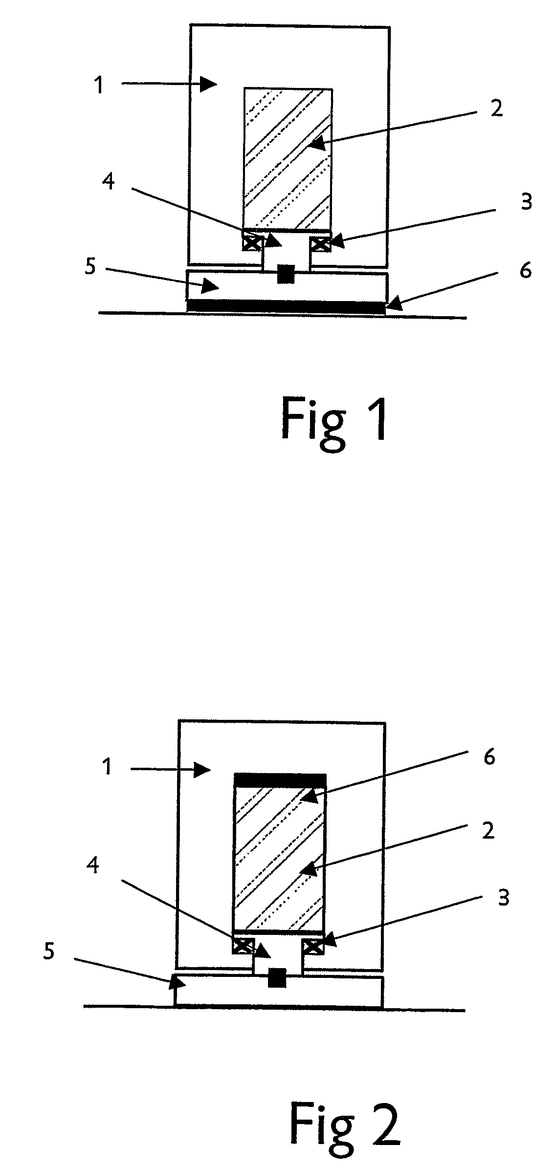
[0096] Referring first to FIGS. 1 and 2, the actuator is essentially as described in our co-pending International Patent Application PCT / GB02 / 01111, having a housing 1 which serves also as a reaction mass and which contains a core 2 consisting of an element of a giant magnetostrictive material (“GMM”) surrounded by an electromagnetic coil and located between permanent magnets. The element is pre-stressed by springs 3 and coupled to a pusher 4 which Is in turn connected to a foot 5, which in use is pressed against a surface into which the acoustic wave is to be transmitted. A piezoelectric sensing element 6 is incorporated into the actuator to sense acoustic signals in the surface to which the actuator is attached. In the example shown in FIG. 1, the sensing element 6 is provided on the external surface of the foot 5, while in the example shown in FIG. 2, the sensing element is located between the core 2 and the internal surface of the housing 1.

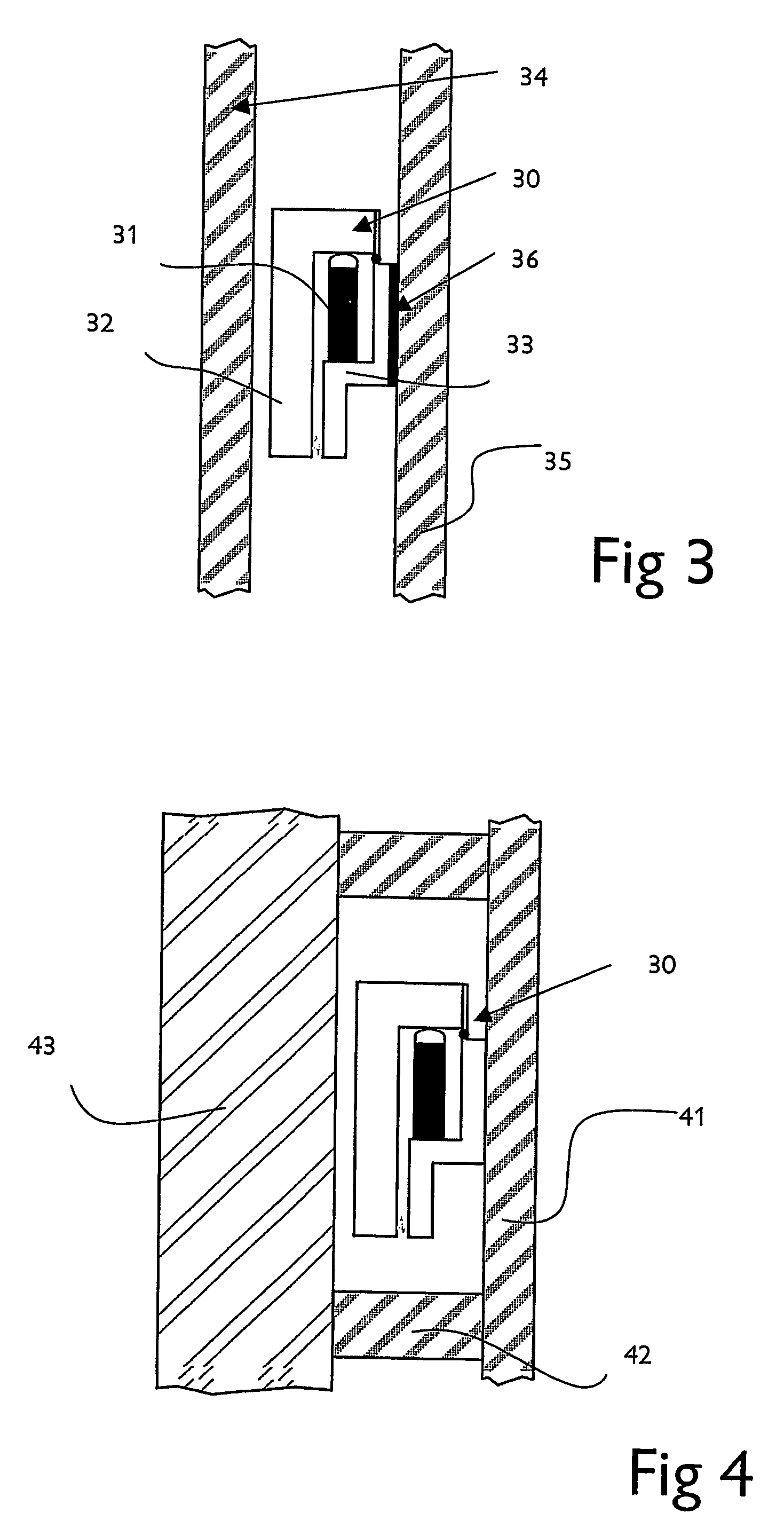
[0097]FIGS. 3 and 4 illustrate a diff...


PUM


Abstract

An audio system comprises, according to one aspect of the invention, an audio frequency actuator coupled to a body so as to cause the body to radiate sound when an audio signal is supplied to the actuator by a controller, and an acoustic sensor coupled to said body or to an adjacent body so as to sense acoustic vibrations in said body, the sensor being connected to the controller, whereby the controller is arranged to change the audio signal supplied to the actuator according to the vibrations sensed by the sensor. Another aspect provides an audio system comprising an audio frequency actuator coupled to a body so as to cause the body to radiate sound when an audio signal is supplied to the actuator by a controller, and an acoustic sensor coupled to said body or to an adjacent body so as to sense acoustic vibrations in said body, the sensor being connected to the controller, whereby the controller is arranged to detect predetermined characteristics of the sensed acoustic vibrations and to output an alerting signal in response thereto.

Description

FIELD OF THE INVENTION [0001] This invention relates to an audio system. In one aspect, the invention relates to the conversion of an otherwise non-responsive body, for example a rigid or flexible panel, by the addition of high-force, wide-band acoustic actuators to create a smart surface that can emit and / or receive acoustic signals for the purpose of providing discreet audio or noise masking, or for sensing attack for security purposes. The audio system of this invention can be described as providing a single smart surface with Its associated acoustic locus properties or an enclosed volume when a multiplicity of such panels is activated. [0002] The volume to be influenced can be either a singular or multiple arrangements of smart surfaces, fixed or moving. [0003] An additional aspect of this invention also relates to the control of noise levels emitted from these smart surfaces or structural elements to avoid environmental noise pollution and create areas (or volumes) of sound mas...

Claims


Application Information

Patent Timeline
Patent Type & Authority Applications(United States)
IPC IPC(8): A61F11/06H03B29/00G10K11/16G10K11/172H04R3/00H04R7/04
CPCG10K11/172H04R3/002H04R7/045H04R2201/021H04R2499/13
Inventor SMITH, BRIAN DOUGLASASTON, MARTIN GEOFFREY
Owner FEONIC
Why Eureka
Try Eureka