
Detector for determining a position of at least one object

a technology of at least one object and a detector, applied in the field of detectors, can solve the problems of resource and cost, ambiguity in the measurement of longitudinal positions, etc., and achieve the effects of efficient filling of pores, greater surface area, and greater amount of dyes

Active Publication Date: 2017-07-20
BASF AG
View PDF0 Cites 41 Cited by
  • Summary
  • Abstract
  • Description
  • Claims
  • Application Information

AI Technical Summary

Benefits of technology

The patent text describes devices that use a transversal optical sensor to generate position coordinates based on the electrical currents through partial electrodes. These devices can be used in various applications such as manufacturing, logistics, quality control, and identification of objects. The devices can also be combined with 3D printers for rapid prototyping and detect the shape of articles for anti-product piracy and anti-counterfeiting purposes. The technical effects of these devices include improved positioning accuracy and efficiency in production processes and improved quality control and identification of objects.

Problems solved by technology

However, the usage of only one transparent or partially transparent position sensor in order to determine a longitudinal position of the object may yield to the problem of ambiguity of the measurement of the longitudinal position, in particular if the object is positioned before or behind a focus point or area.
However, the usage of multiple, in particular three or more, longitudinal optical sensors to measure the longitudinal position of the object to achieve a high degree of accuracy and an unambiguous measurement, may be resource and cost intensive.

Method used


Image

  • Detector for determining a position of at least one object
  • Detector for determining a position of at least one object
  • Detector for determining a position of at least one object

Examples


Embodiment Construction

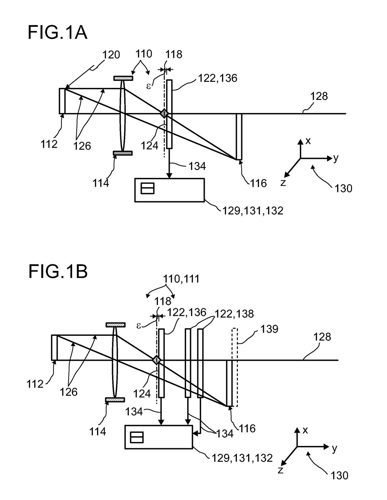
[0389]In FIG. 1 A, an exemplary embodiment of a detector 110 for determining a position of at least one object 112 is depicted. The detector 110 in this embodiment or other embodiments of the present invention, may be a stand-alone-detector or may be combined with one or more other detectors. As an example, the detector 110 may form a camera or may be part of a camera. Additionally or alternatively, the detector 110 may be part of a human-machine interface, an entertainment device or a tracking system. Other applications are feasible.

[0390]The detector 110 comprises at least one transfer device 114 for imaging the object into an image plane 116. The transfer device 114 has a focal plane 118. The transfer device 114 may have focusing or defocusing effects onto the light beam 126. The transfer device 114 may be realized as one or more of a focusing lens; a defocusing lens; a camera lens; a curved mirror; a diaphragm. In this embodiment, the transfer device 114 may be or may comprise a...


PUM


Abstract

A detector (110) for determining a position of at least one object (112), the detector (110) comprising: at least one GP transfer device (114) for imaging the object (112) into an image plane (116), the transfer device (114) having a focal plane (118), at least one longitudinal optical sensor (122), wherein the longitudinal optical sensor (122) has at least one sensor region (124), wherein the longitudinal optical sensor (122) is at least partially transparent, wherein the longitudinal optical sensor (122) is designed to generate at least one longitudinal sensor signal in a manner dependent on an illumination of sensor region (124) by at least one light beam propagating from the object to the detector (110), wherein the longitudinal sensor signal, given the same total power of the illumination, is dependent on a beam cross-section of the light beam in the sensor region (124); and at least one evaluation device (129), wherein the evaluation device (129) is designed to generate at least one item of information on a longitudinal position of the object (112) by evaluating the longitudinal sensor signal. Herein the at least one longitudinal optical sensor (122) comprises a focal longitudinal optical sensor (136), wherein the focal longitudinal optical sensor (136) at least substantially is arranged in the focal plane (118).

Description

FIELD OF THE INVENTION[0001]The invention relates to a detector for determining a position of at least one object, a human-machine interface, an entertainment device for carrying out at least one entertainment function, a tracking system, a camera, a method for determining a position of at least one object and various uses of the detector. Such devices and such methods can be employed for example in various areas of daily life, traffic technology, production technology, security technology, medical technology, entertainment technology or in the sciences. Additionally or alternatively, the application may be applied in the field of mapping of spaces, such as for generating maps of one or more rooms, one or more buildings or one or more streets. Further, the detector may form a camera or may be part of a camera for imaging at least one object. However, other applications are also possible in principle.PRIOR ART[0002]A large number of detectors configured to determine a position of an ...

Claims


Application Information

Patent Timeline
Patent Type & Authority Applications(United States)
IPC IPC(8): G01C3/32G01S17/86G01S17/89G01S17/931
CPCG01C3/32G01S17/46G01S17/89G01B11/026G01S7/481G01S17/86G01S17/931G01S5/16G01S11/12
Inventor SEND, ROBERTBRUDER, INGMARIRLE, STEPHANTHIEL, ERWIN
Owner BASF AG
Learn More