Anti-Fatigue Shock Mitigation System

Active Publication Date: 2017-07-13
BEASLEY TODD +3
View PDF3 Cites 3 Cited by
  • Summary
  • Abstract
  • Description
  • Claims
  • Application Information

AI Technical Summary

Benefits of technology

The present invention is an improved seat suspension control system and method for suspending a seat using a pneumatic cylinder, an air compressor, solenoid valve and a microelectromechanical system (MEMS) based control. The suspension is activated by charging the cylinder with a compressible gas, preferably air, using an electrically operated on-board compressor. The compressed gas inside the cylinder acts as the spring force working against the applied load and the MEMS measures the severity of the disturbance and a control algorithm decides to either allow the cylinder pressure to rise or vent to attenuate the disturbance. The system may further comprise a mounting flange secured to the cylinder and guide members utilized to prevent rotation of the piston with respect to the cylinder. The technical effects of the present invention are improved comfort and vibration isolation properties due to the varying spring rate determined by the internal pressure of the gas cylinder and the ability to measure and control the suspension based on the severity of the disturbance.

Problems solved by technology

One such hazard often associated with powered boat seats or helm chairs are the exposed power conduits that come out from the pedestal to an electrical outlet.

Method used


Image

  • Anti-Fatigue Shock Mitigation System
  • Anti-Fatigue Shock Mitigation System
  • Anti-Fatigue Shock Mitigation System

Examples


Embodiment Construction

[0035]Detailed descriptions of the preferred embodiment are provided herein. It is to be understood, however, that the present invention may be embodied in various forms. Therefore, specific details disclosed herein are not to be interpreted as limiting, but rather as a basis for the claims and as a representative basis for teaching one skilled in the art to employ the present invention in virtually any appropriately detailed system, structure or manner.

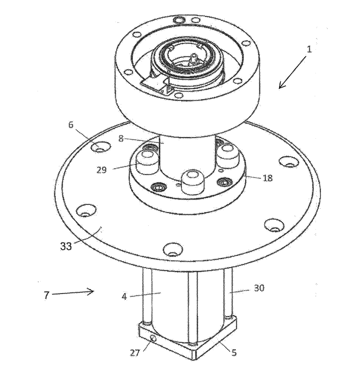
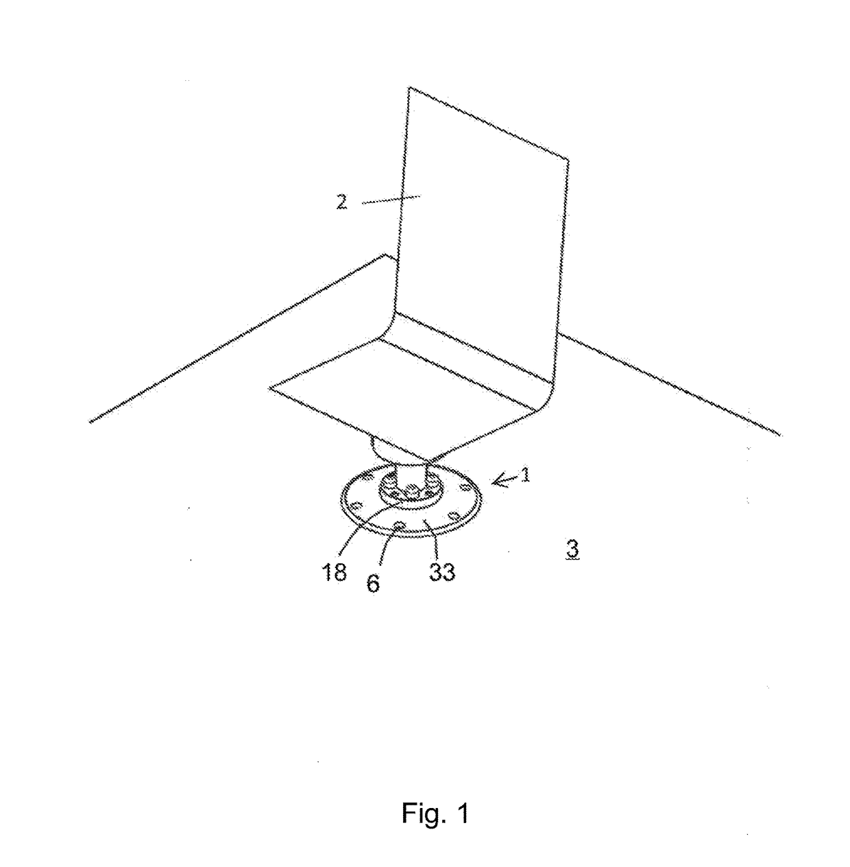
[0036]FIG. 1 shows a simplified view of a seat 2 attached to the support assembly, shown generally as 1, of the present invention.

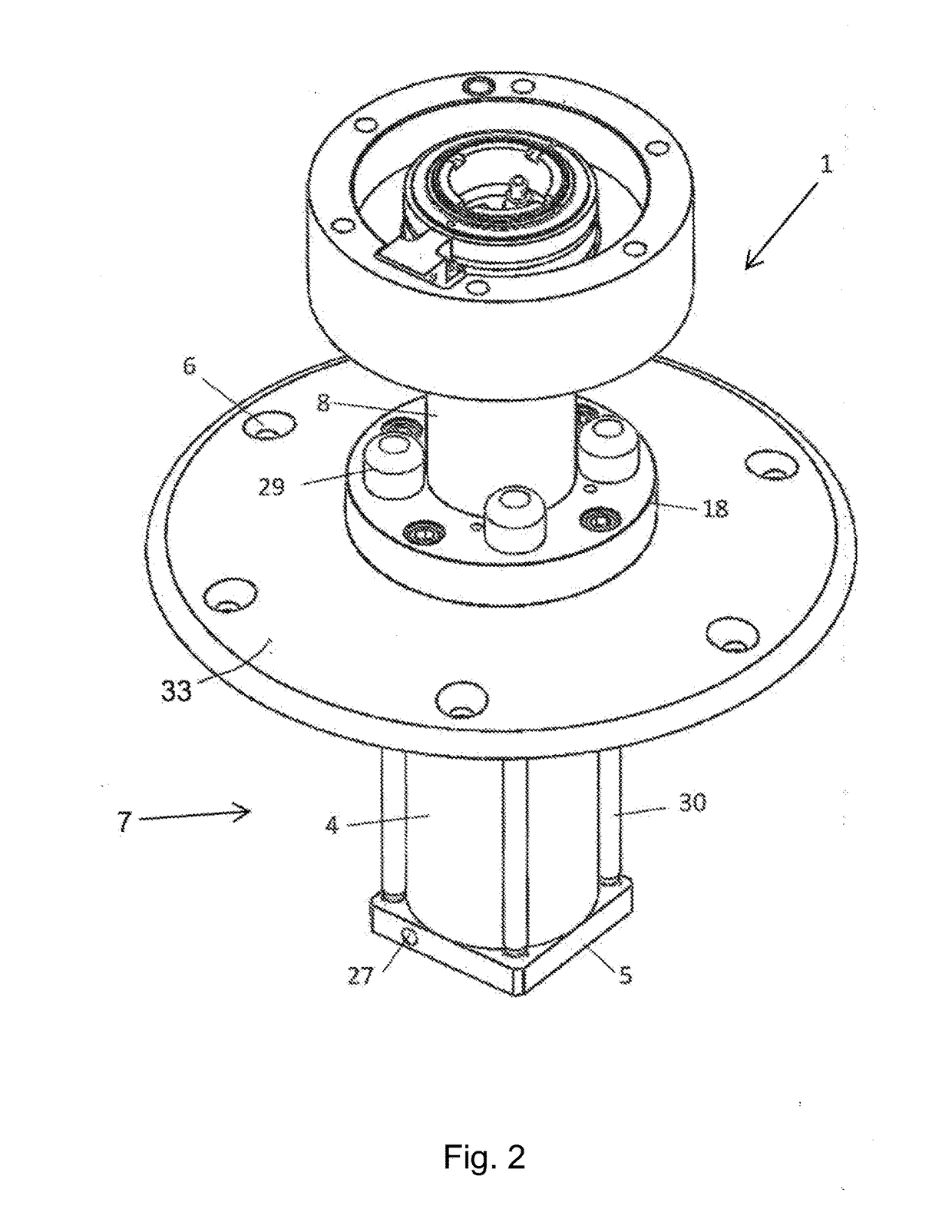
[0037]Referring to FIG. 1 and FIG. 2, the exemplar embodiment presented shows the seat support assembly 1 on which is installed a helm seat 2 of a marine craft. The seat suspension system may also be adopted for other applications where it is desirable to isolate vehicle operators from vibrations transmitted through rigid frame vehicles such as agricultural machinery and earth moving equipment.

[0038]Partic...


PUM


Abstract

A control system and method for the seat suspension described herein utilizes a pneumatic cylinder which forms the shock absorber, an air compressor, solenoid valve and a microelectromechanical system (MEMS) based control. In operation, the pneumatic cylinder is filled with a compressible gas and sustained under pressure for the purpose of supporting the static weight of the occupant as well as providing comfort by reducing transmitted vibrations and high acceleration from external disturbances. A control process utilizes vibration data from the MEMS to adjust the gas cylinder pressure accordingly to reduce and damp the undulations of the supported mass.

Description

CROSS-REFERENCE TO RELATED APPLICATION[0001]This application claims priority to U.S. Application No. 62 / 026,333, filed Jul. 18, 2014, the disclosure of which is incorporated herein by reference for all purposes.BACKGROUND OF THE INVENTION[0002](1) Field of the Invention[0003]The present invention relates generally to seat suspension systems and more specifically to a pneumatic system with electronic control.[0004](2) Description of the Prior Art[0005]Conventional seat suspension systems use coil springs to absorb transmitted vibration sometimes in conjunction with hydraulic cylinder as dampers. Other suspensions use pneumatic systems that utilize flexible rubber bellows or a rolling diaphragm connected to a separate air reservoir via a flow restriction. In this type of prior art system, the stiffness of the pneumatic spring is determined by the compressed gas pressure and the flow restriction introduces damping. The control system for these devices commonly uses direct pressure meas...

Claims


Application Information

Patent Timeline
IPC IPC(8): B60N2/52B63B29/06B60N2/50
CPCB60N2/525B63B2029/043B63B29/06B60N2/502B60N2/509
Inventor BEASLEY, TODDJUAN, ALEJANDRO J.LARSEN, SVENTARDIFF, DALE
Owner BEASLEY TODD
Why Eureka
Try Eureka