
Transparent conductive film and method for producing transparent conductive film

a technology of transparent conductive film and transparent conductive film, which is applied in the direction of removing conductive materials by irradiation, identification means, instruments, etc., can solve the problems of low resistance, difficult to achieve both an appropriate visibility and an appropriate visibility, and significant increase in light reflection. , to achieve the effect of low electrical resistance, excellent wiring adhesion and high reliability

Active Publication Date: 2017-06-15
FUJIFILM CORP
View PDF4 Cites 0 Cited by
  • Summary
  • Abstract
  • Description
  • Claims
  • Application Information

AI Technical Summary

Benefits of technology

[0009]In view of the above problems, an object of the present invention is to provide a transparent conductive film, which can achieve both of an appropriate visibility and a low resistance due to a specific surface shape of a thin metal wire, and thereby can be suitably used in a touch panel, a display device, or the like.
[0046]In addition, in the display device of the present invention having the display screen and the transparent conductive film attached thereto, the wiring pattern is less visible, and the transparent conductive film exhibits a low electrical resistance and an excellent wiring adhesion, thereby resulting in high reliability.

Problems solved by technology

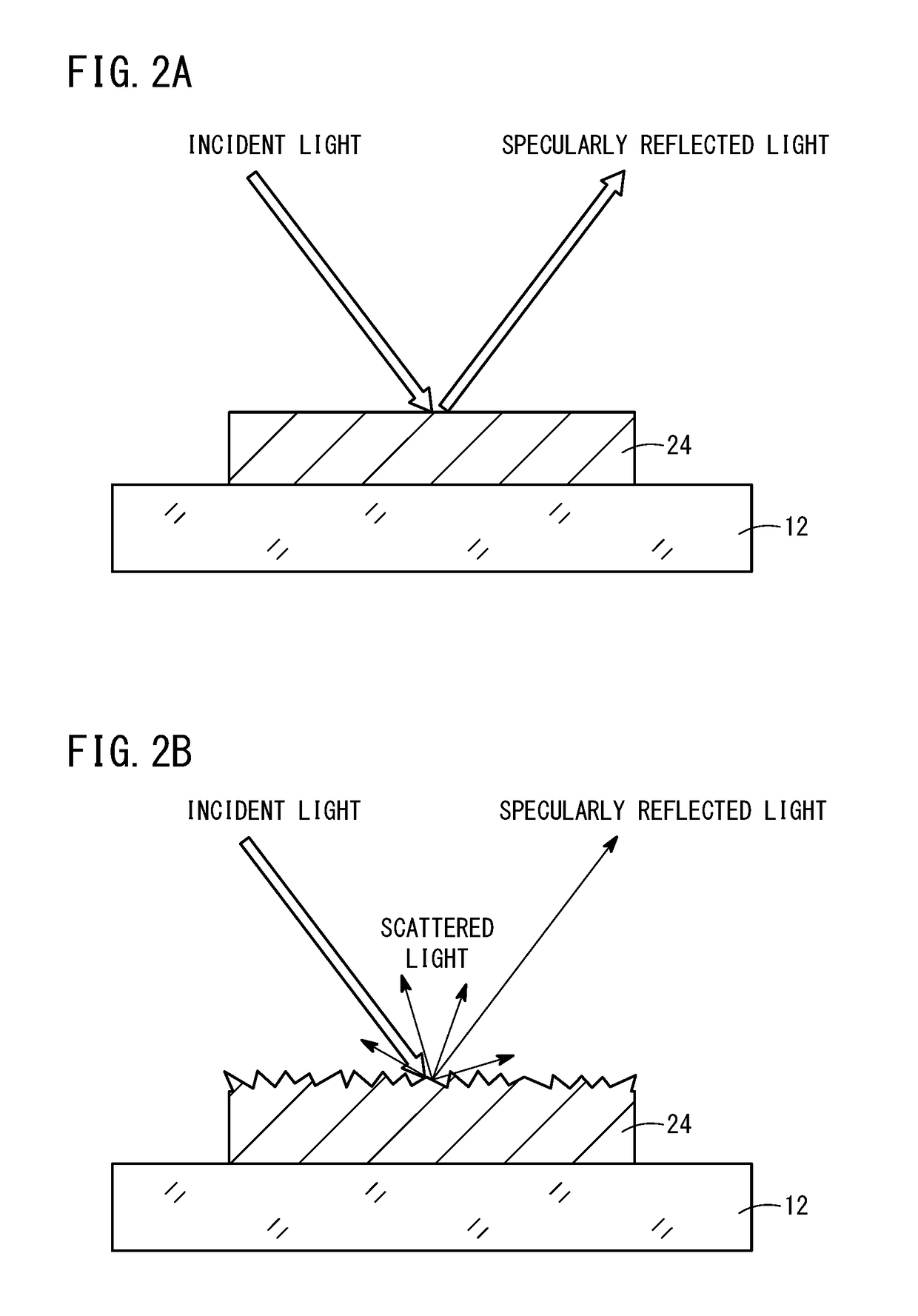
Though the resistance can be reduced by increasing the volume content of the metal in a calender treatment or the like, this treatment results in a significantly increased light reflection.
Thus, it is difficult to achieve both an appropriate visibility (low visibility of the wiring pattern) and a low resistance.

Method used


Image

  • Transparent conductive film and method for producing transparent conductive film
  • Transparent conductive film and method for producing transparent conductive film
  • Transparent conductive film and method for producing transparent conductive film

Examples


examples

[0232]The present invention will be described more specifically below with reference to Examples. Materials, amounts, ratios, treatment contents, treatment procedures, and the like, used in Examples, may be appropriately changed without departing from the scope of the present invention. The following specific examples are therefore to be considered in all respects as illustrative and not restrictive.

first example

[0233]In Examples 1 to 15 and Comparative Examples 1 to 14, various properties were evaluated under various surface shapes of mat members used in a calender treatment.

example 1

[Preparation of Silver Halide Emulsion]

[0234]Liquid 1 was maintained at 38° C. and pH 4.5, and 90% of the total amounts of Liquids 2 and 3 were simultaneously added to Liquid 1 over 20 minutes under stirring to form 0.16-μm nuclear particles. Then, Liquids 4 and 5 were added thereto over 8 minutes, and residual 10% of Liquids 2 and 3 were added over 2 minutes, so that the nuclear particles were grown to 0.21 μm. Further 0.15 g of potassium iodide was added thereto, and the resulting mixture was aged for 5 minutes to complete the particle formation.

Water750mlGelatin8.6gSodium chloride3.1g1,3-Dimethylimidazolidine-2-thione20mgSodium benzenethiosulfonate10mgCitric acid0.7g

Water300 mlSilver nitrate150 g

Water300mlSodium chloride38gPotassium bromide32gPotassium hexachloroiridate (III)5ml(0.005% KCl, 20% aqueous solution)Ammonium hexachlororhodate7ml(0.001% NaCl, 20% aqueous solution)

Water100 mlSilver nitrate 50 g

Water100mlSodium chloride13gPotassium bromide11gPotassium ferrocyanide5mg

[023...


PUM

PropertyMeasurementUnit
distanceaaaaaaaaaa
specular reflectancesaaaaaaaaaa
thicknessaaaaaaaaaa

Abstract

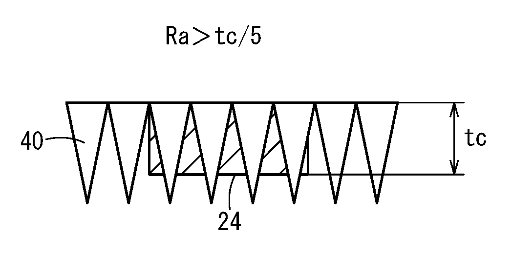
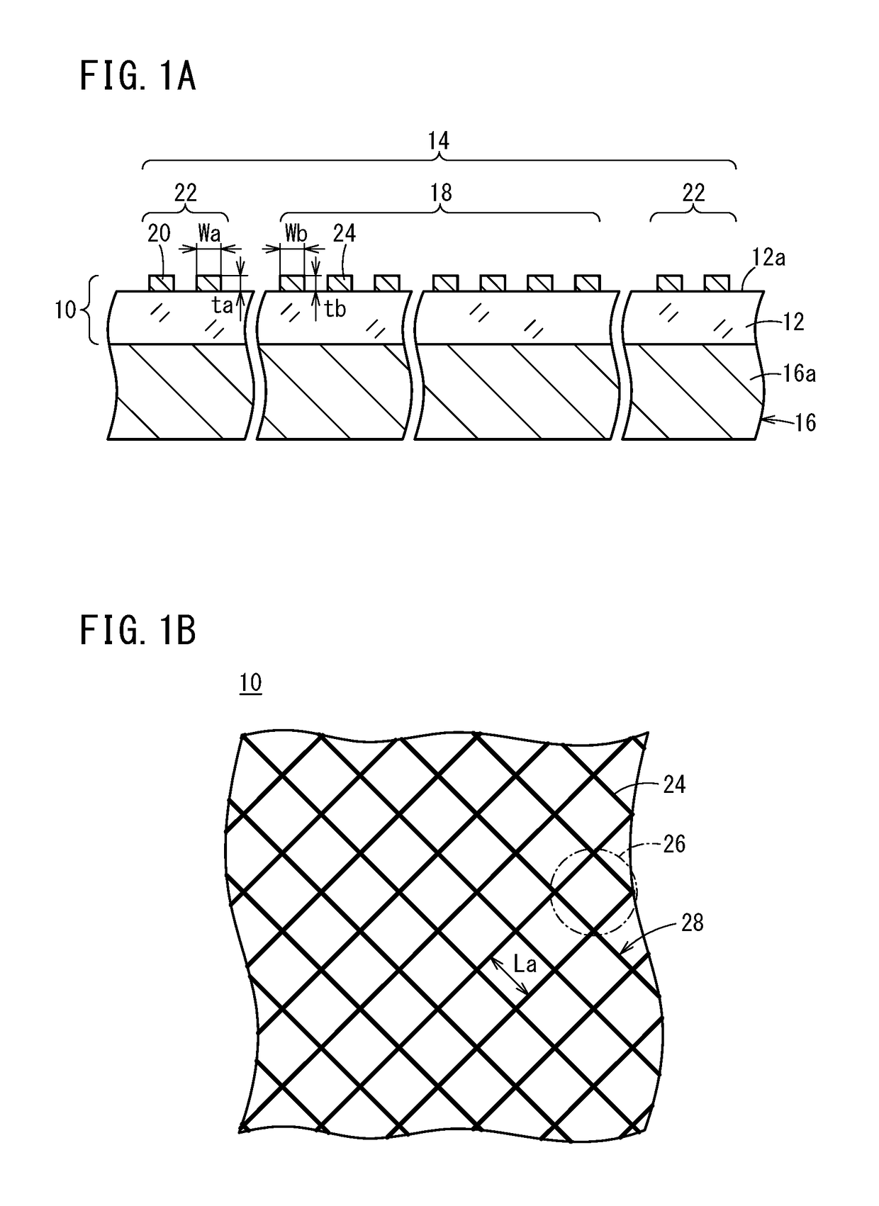
A transparent conductive film comprises a transparent substrate and a metal wiring portion formed thereon. A thin metal wire contained in an electrode portion in the metal wiring portion has a surface shape satisfying the condition of Ra2 / Sm>0.01 μm and has a metal volume content of 35% or more. Ra represents an arithmetic average roughness in micrometers and is equal to or smaller than the thickness of a metal wiring located in a position where the surface roughness is measured. Sm represents an average distance between convex portions and is 0.01 μm or more.

Description

CROSS-REFERENCE TO RELATED APPLICATIONS AND PRIORITY CLAIMS[0001]This application is a Divisional of U.S. application Ser. No. 14 / 947,831 filed on Nov. 20, 2015, which is a Continuation of International Application No. PCT / JP2014 / 062783 filed on May 14, 2014, which was published under PCT Article 21(2) in Japanese, which is based upon and claims the benefit of priorities from Japanese Patent Application No. 2013-110402 filed on May 24, 2013 and Japanese Patent Application No. 2014-045684 filed on Mar. 7, 2014, the contents all of which are incorporated herein by reference.TECHNICAL FIELD[0002]The present invention relates to a transparent conductive film and a method for producing a transparent conductive film.BACKGROUND ART[0003]Metals have high conductivity and therefore are suitable for use in a material for a conductive layer. But at the same time, the metals intensely reflect visible lights, and are unsuitable for use in applications such as touch panel applications, in which a...

Claims


Application Information

Patent Timeline
Patent Type & Authority Applications(United States)
IPC IPC(8): H05K1/09G06F3/041H05K3/02
CPCH05K1/09H05K3/027H05K2203/0502H05K2201/0364G06F3/041H01B1/02G06F3/045Y10T29/49155H10K71/60H10K50/814G09F9/00H05K1/0296H05K3/10H05K2201/09209
Inventor KATAGIRI, KENSUKETAJIRI, SHINHASE, AKIHIKO
Owner FUJIFILM CORP
Learn More