
Method for operating an at least generator-operable electric motor and means for the implementation thereof

a technology of electric motor and generator, which is applied in the direction of electric generator control, electric devices, transportation and packaging, etc., can solve the problems of low accuracy, large output voltage, and low accuracy at the generator, and achieves low cost, simple and inexpensive implementation, and robust use

Inactive Publication Date: 2017-06-08
SEG AUTOMOTIVE GERMANY GMBH
View PDF3 Cites 1 Cited by
  • Summary
  • Abstract
  • Description
  • Claims
  • Application Information

AI Technical Summary

Benefits of technology

The present invention relates to a method for reducing stress on current valves in electrical systems, such as power distribution systems. The method uses a maximum value that is initially set at a zero value to minimize the stress on current valves. The maximum value is only increased for phases where there is no longer a corresponding zero crossing of the phase current. The method also includes setting a steepness for the nonlinear function, which determines the minimum of the phase current. The steepness is set in amperes per second and ensures that the minimum of the phase current is missed at most by a maximum of a certain value. The method can be easily integrated into existing systems and is robust against tolerances and interference. The invention also provides a software implementation of the method that is cost-effective and can be downloaded via computer networks.

Problems solved by technology

A load discontinuity in the connected network, for example due to connection or disconnection of a load, results in a load discontinuity at the generator.
But because the power delivery of the generator cannot be modified arbitrarily quickly due to the inductance of the excitation field, the generator current initially remains approximately constant, which in the context of a load dump can result in an appreciable increase in the output voltage.
If a battery is not present, however, the output voltage then rises very quickly and is capable of damaging electrical system components and / or the generator.
The result is that the electric machine is internally short-circuited but not the connected network.
Because of the asymmetry just explained, in some circumstances high currents must be switched; this causes corresponding stress on the participating current valves.
This can result in damage to those current valves.
The shutoff of the current valves of a phase can, however, bring about an additional asymmetry in the phases that still have switched-on current valves, due once again to a higher, non-decaying DC component.
A corresponding result can also be caused, however, simply by the DC components impressed upon initiation of the phase short circuit.
Diodes are likewise current valves, but are not controllable.
A rotation speed dependence is significant in particular because corresponding generators can be operated in extremely wide rotation speed ranges of, for example, 1500 to 20,000 revolutions per minute, so that constant times would always need to be designed for the “worst case” rotation speed (which is the lowest rotation speed), which would result in superfluous delay times at higher rotation speeds.

Method used


Image

  • Method for operating an at least generator-operable electric motor and means for the implementation thereof
  • Method for operating an at least generator-operable electric motor and means for the implementation thereof
  • Method for operating an at least generator-operable electric motor and means for the implementation thereof

Examples


Embodiment Construction

[0038]In the Figures, elements corresponding to one another are labeled with identical reference characters and are not explained repeatedly.

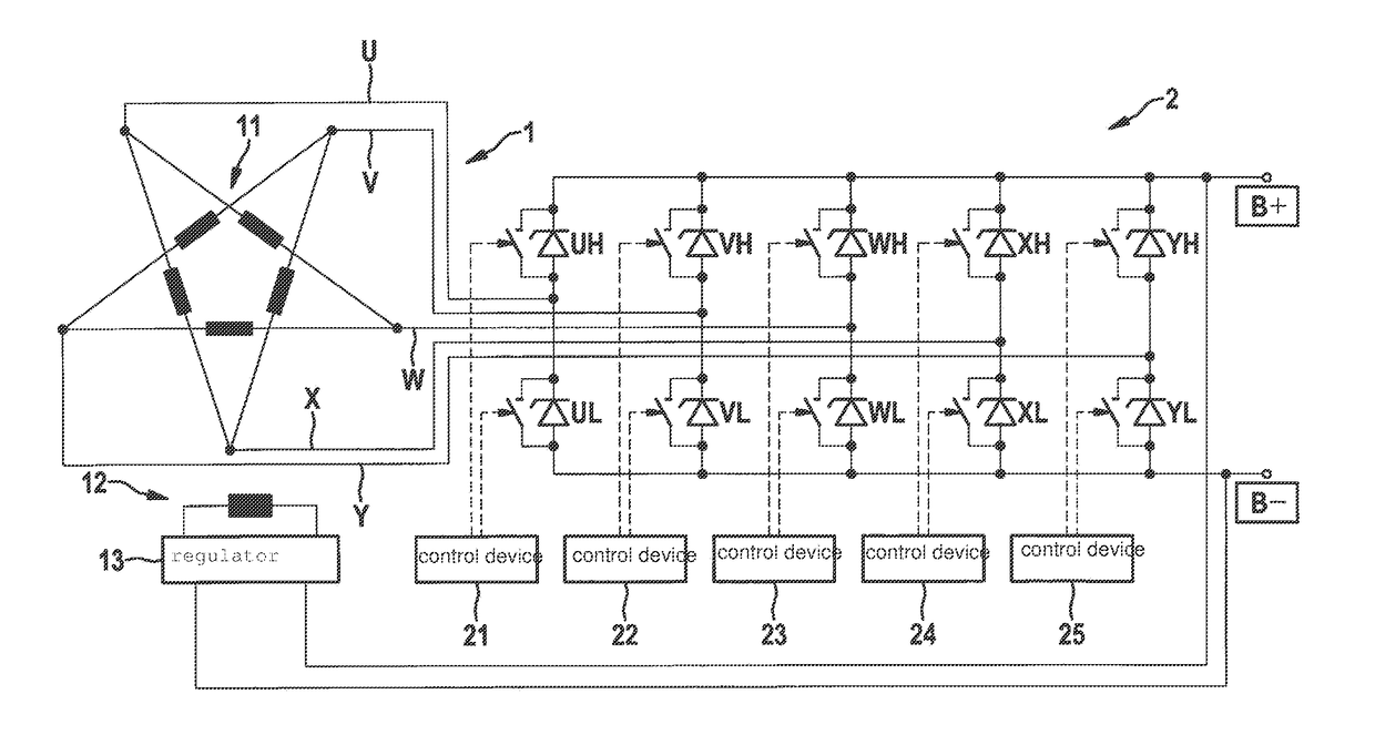
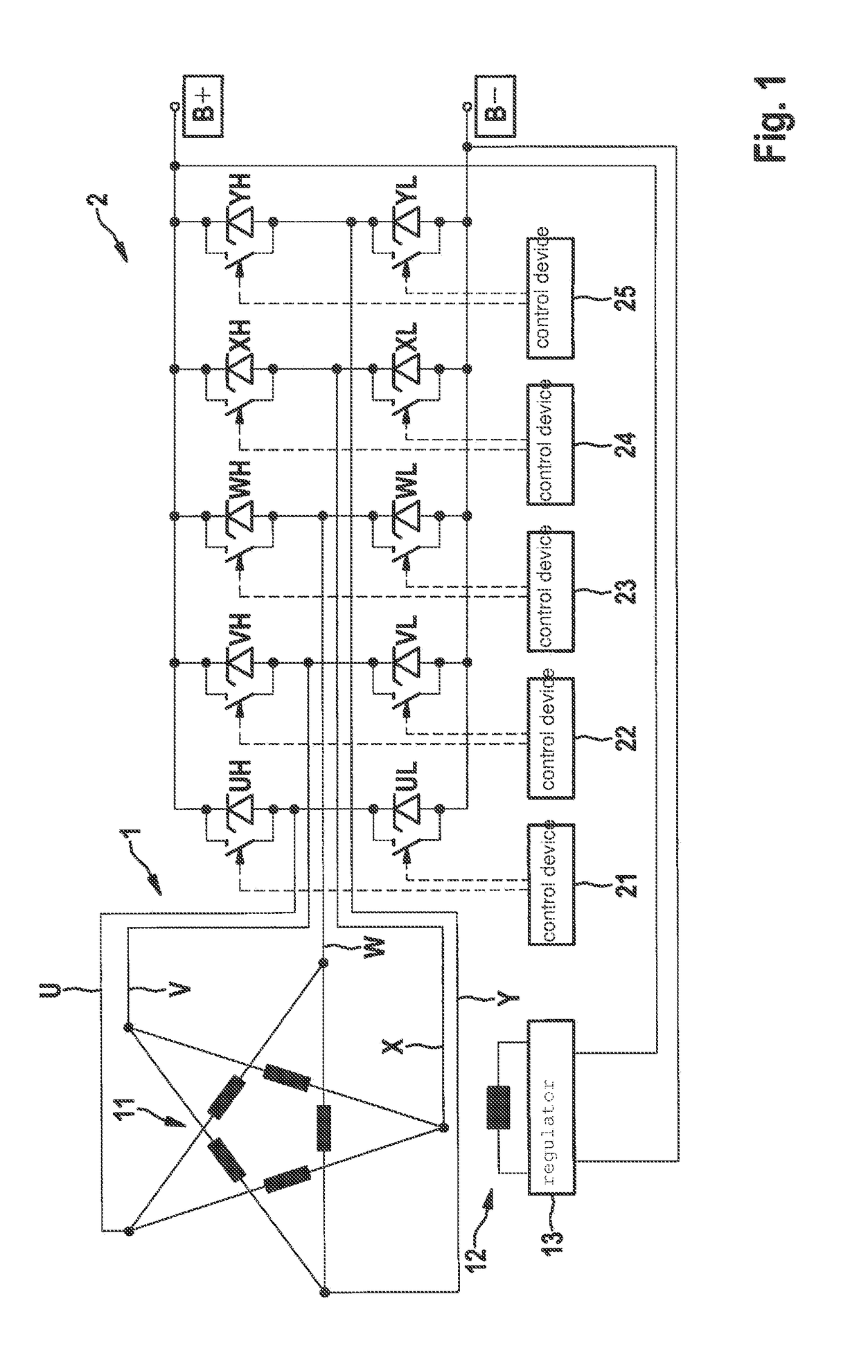
[0039]FIG. 1 schematically illustrates an assemblage, having a generator 1 and an active bridge rectifier 2, that can be the basis of an embodiment of the present invention.

[0040]Generator 1 encompasses a stator 11 configured with five phases and as a pentagram circuit, and a rotor 12. The individual windings of stator 11 and of rotor 12 are not labeled separately. Generator 1 is connected at five phase terminals U to Y, via respective controllable current valves capable of being switched on and shut off (here labeled UL to YL and UH to YH), respectively to first DC voltage terminal B− and to a second DC voltage terminal B+. The method according to the present invention will be described below with reference to initiation of a phase short circuit in current valves UL to YL of a “low-side” rectifier branch, but can also be carried out with curre...


PUM


Abstract

A method for controlling a multi-phase electric machine, whose phase terminals in an active bridge rectifier are respectively connected, via controllable first current valves, to a first DC voltage terminal and via second current valves to a second DC voltage terminal. The method includes switching on the first current valves when an output voltage between the first DC voltage terminal and the second DC voltage terminal has exceeded an upper threshold value at an exceedance point in time, and shutting off the first current valves again only once the output voltage has subsequently fallen below a lower threshold value at a shortfall point in time. The first current valves are shut off again after the shortfall point in time individually, and each only when a respective indication value, which characterizes a current flow in the phase terminal associated with the respective current valve, exhibits a predetermined property.

Description

FIELD[0001]The present invention relates to a method for operating an electric machine, operable at least in generator mode and having an active bridge rectifier, and to an implementation thereof.BACKGROUND INFORMATION[0002]Generators of the claw pole type, having passive bridge rectifiers, are conventionally utilized in passenger cars. The output of such generators is adjusted via the excitation field, and that in turn via the excitation current. The output voltage of the generator can be held constant, regardless of network load, rotation speed, and temperature, by regulating the excitation field.[0003]When what is discussed hereinafter is simply a “generator,” this can refer to an electric machine operable in both generator mode and motor mode, for example a so-called “starter generator.” The present invention is suitable not only for claw pole-type generators but instead for all electric machines operable at least in generator mode. In passenger cars, bridge rectifiers in a six-...

Claims


Application Information

Patent Timeline
Patent Type & Authority Applications(United States)
IPC IPC(8): H02H7/06H02P9/10H02P9/00
CPCH02H7/067H02P9/102H02P9/107H02P9/006H02P29/032B60L3/0061H02M1/38Y02T10/64B60L2240/42
Inventor SCHMIDT, MATTHIAS
Owner SEG AUTOMOTIVE GERMANY GMBH
Learn More