
Variable Compression Connecting Rod

Inactive Publication Date: 2017-06-08
MEACHAM G B KIRBY
View PDF0 Cites 8 Cited by
  • Summary
  • Abstract
  • Description
  • Claims
  • Application Information

AI Technical Summary

Benefits of technology

This patent describes new methods for providing two-stage engine compression using eccentric bushings to change connecting rod length, which provide reliable and consistent rod length shifts. The invention uses a switchable one-way clutch mechanism to control the eccentric rotation, which ensures that the full travel may be accumulated over more than one force reversal cycle, thus minimizing changes to engines and simplifying controls. Additionally, a second aspect of the invention modifies the squeeze film interface to reduce peak cylinder loads on the eccentric latching mechanism while facilitating the inertial load driven eccentric rotation from low to high compression. The technical effects of this patent include more reliable and consistent rod length shifts, simplified controls, and minimized changes to engines.

Problems solved by technology

Above the knock limit, a portion of the fuel-air mixture in the combustion chamber undergoes very rapid bulk combustion that produces a pressure spike resulting in audible noise and potential engine damage.
Late or retarded ignition timing from the maximum torque value reduces knock, but also reduces engine efficiency and increases heat transfer losses.
This leads to lower than optimum gas charge temperature and pressure at the end of the compression stroke, and consequent reduced efficiency.
Since the typical duty cycle of light duty vehicles consists of predominantly light load operation, the non-optimum compression ratio results in significant efficiency losses.
Although there are exceptions, typical prior art mechanisms are self-powered in that the alternating compressive and tensile forces on the connecting rod and eccentric bushing during the engine cycle generate torque that rotates the eccentric to change the effective rod length.
This causes a loss of the desired rotation, and may result in situations in which the eccentric rotational position cycles with each rod force direction, and full rotation and latch engagement is either slow or never completed.
Such unproductive cycling may also cause wear and noise.
Since maximum compressive rod forces include compression and power stroke gas loading and are typically much larger than primarily inertial tensile rod forces, it may be more difficult to lengthen the rod and increase the compression ratio.
While not wishing to be bound by theory, it is believed that squeeze film lubrication is an important component of piston wrist pin lubrication, and is similarly important in determining the instantaneous friction coefficient μ between the eccentric and the rod, and that it is not adequately addressed in the prior art.
Since the clamping load is constant rather than periodically reversing, these experiments do not provide information on transient squeeze film lubrication effects in which the bearing is fully hydrodynamic and there is no metal to metal contact.
Conversely, transient low friction hydrodynamic bearing effects have the negative effect of increasing the torque load on the eccentric latch mechanism from cylinder pressure loading, particularly when maintaining maximum rod length during high compression operation.
In summary, prior art eccentric bushing variable compression connecting rods may not achieve reliable length shifts under all conditions, and have squeeze film bearing transients in the journal bearing between the connecting rod small end and eccentric bushing that are counterproductive in some operating modes.

Method used


Image

  • Variable Compression Connecting Rod
  • Variable Compression Connecting Rod
  • Variable Compression Connecting Rod

Examples


Embodiment Construction

[0052]Upon examination of the following detailed description the novel features of the present invention will become apparent to those of ordinary skill in the art or can be learned by practice of the present invention. It should be understood that the detailed description of the invention and the specific examples presented, while indicating certain embodiments of the present invention, are provided for illustration purposes only. Various changes and modifications within the spirit and scope of the invention will become apparent to those of ordinary skill in the art upon examination of the following detailed description of the invention and claims that follow.

[0053]The prior art and the invention are described with reference to four cycle internal combustion engines, but it is to be understood that the invention is applicable to other reciprocating engines, pumps and compressors that might benefit from variable compression. In the description “upper”, “top”, “above” and “head” refe...


PUM


Abstract

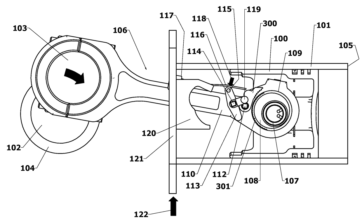
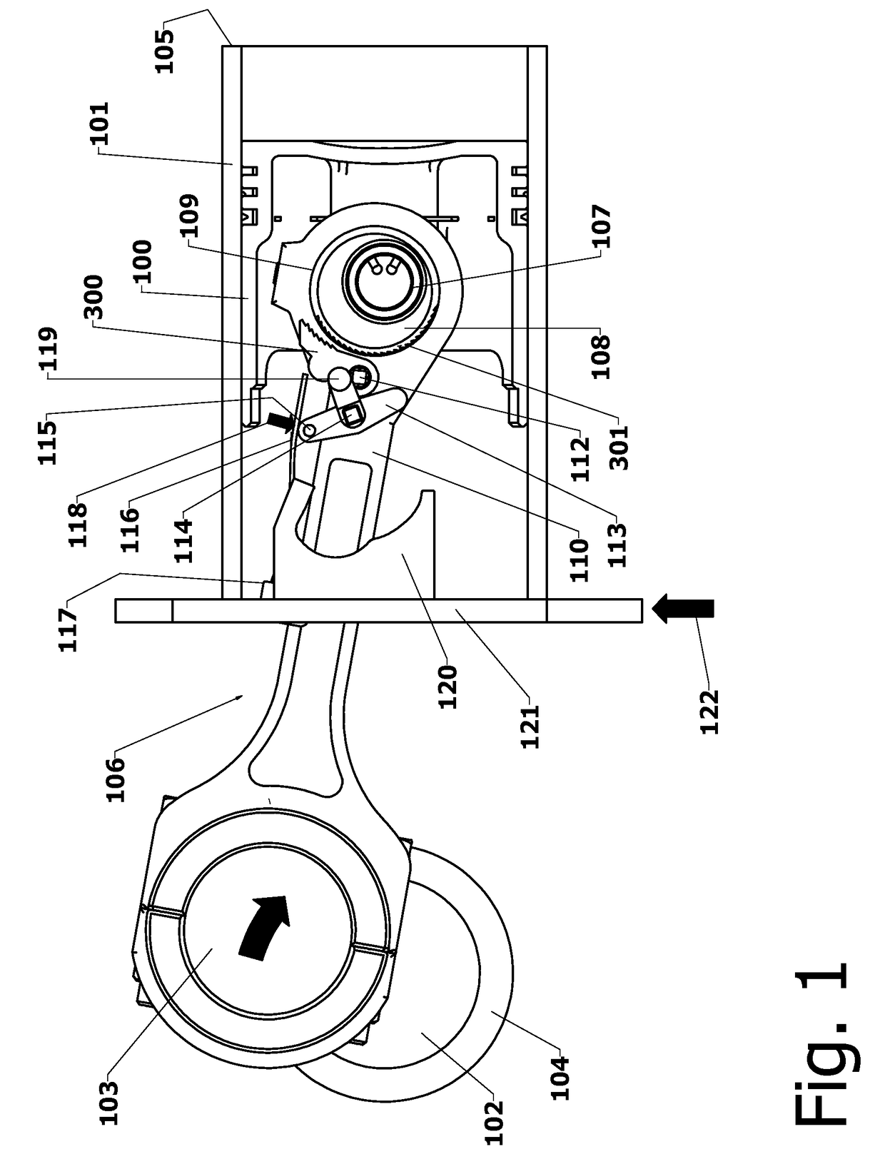
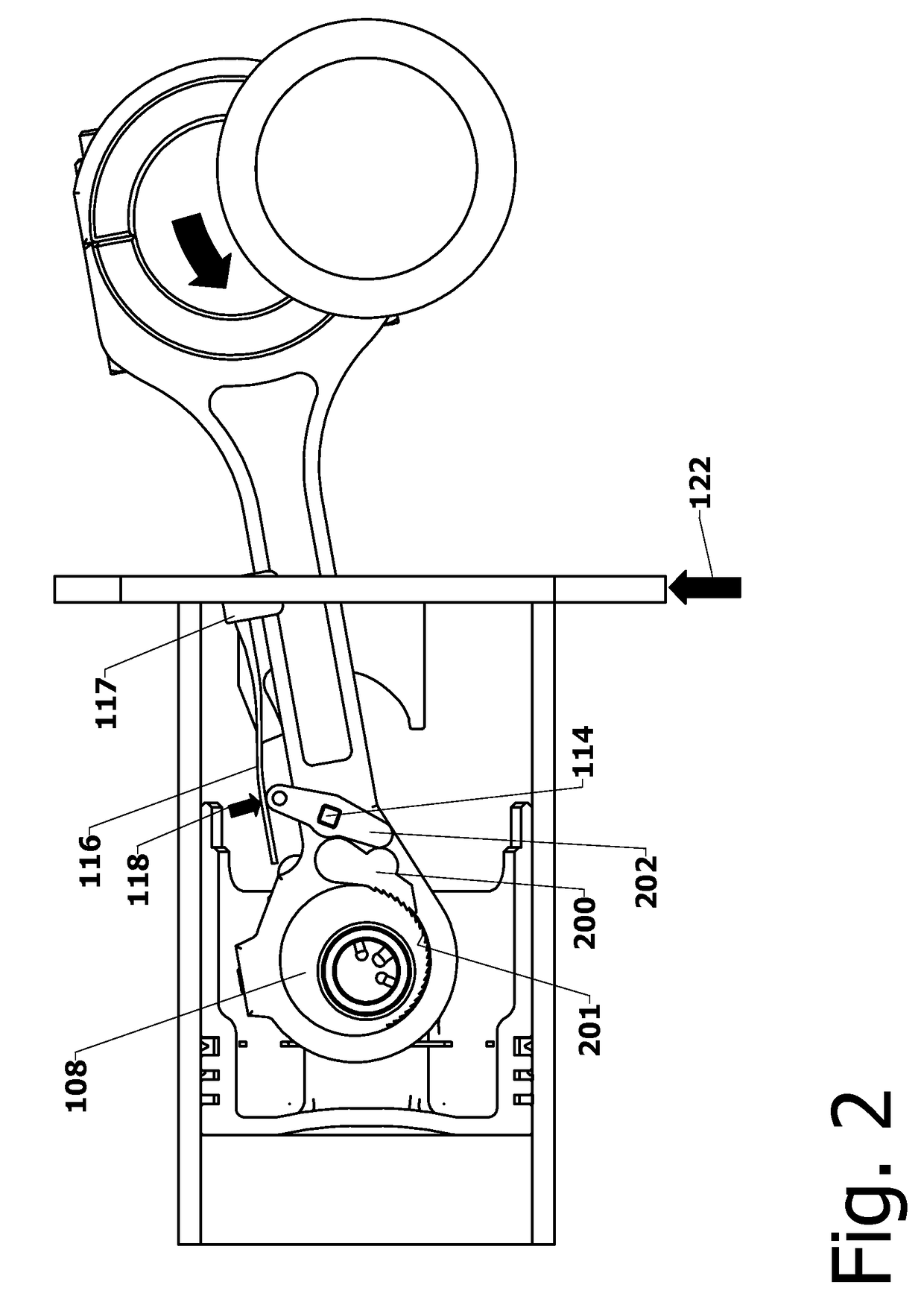
The present invention is directed to improved designs and methods for improving engine fuel efficiency by providing two-stage engine variable compression in running engines using connecting rod force reversals to rotate eccentric bushings to change the connecting rod length. Compression ratio changes are initiated by shifting a block-mounted cam such that it engages and flips a bi-stable toggle on the connecting rod. The clutch mechanism latches the eccentric at the eccentric rotation end point, whereupon the connecting rod acts as a rigid rod. The invention includes novel configurations of the lubricated journal bearing between the connecting rod and the eccentric that modify the squeeze film bearing effects and resulting friction. These configurations reduce the peak eccentric torque carried by the clutch mechanism while facilitating eccentric rotation at lower torque.

Description

FIELD OF THE INVENTION[0001]The present invention is directed to improving engine fuel efficiency by providing adjustable length internal combustion engine connecting rods that link the engine crankshaft to the pistons, wherein the rod length may be changed in a running engine to raise or lower the compression ratio as a function of engine operating conditions. More specifically, the invention is directed to two-stage adjustable length connecting rods in which the adjustable element is an eccentric connection of the rod end to the piston wrist pin that is actuated by the periodically reversing gas and inertial dynamic forces acting on the rod and eccentric assembly, and latched in either of two positions resulting in two different effective rod lengths and corresponding compression ratios.BACKGROUND OF THE INVENTION[0002]The present invention comprises improvements to generally known two-stage adjustable length connecting rods in which the adjustable element is an eccentric connecti...

Claims


Application Information

Patent Timeline
IPC IPC(8): F02B75/04F16D41/16F16C7/06
CPCF02B75/045F16D41/16F16C7/06F02D15/02F16C3/28F16C2360/22
Inventor MEACHAM, G.B. KIRBY
Owner MEACHAM G B KIRBY
Learn More