
Method and system for generating minimal cut-sets for highly integrated large systems

a large system and high-integration technology, applied in the field of reliability assessment, can solve the problems of time-consuming process for cutting-set generation, method which is time-consuming, method is still time-consuming for large systems, etc., and achieve the effect of high efficiency and accuracy

Active Publication Date: 2017-05-25
THE BOEING CO
View PDF3 Cites 4 Cited by
  • Summary
  • Abstract
  • Description
  • Claims
  • Application Information

AI Technical Summary

Benefits of technology

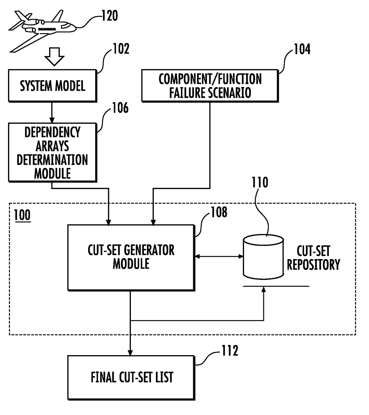
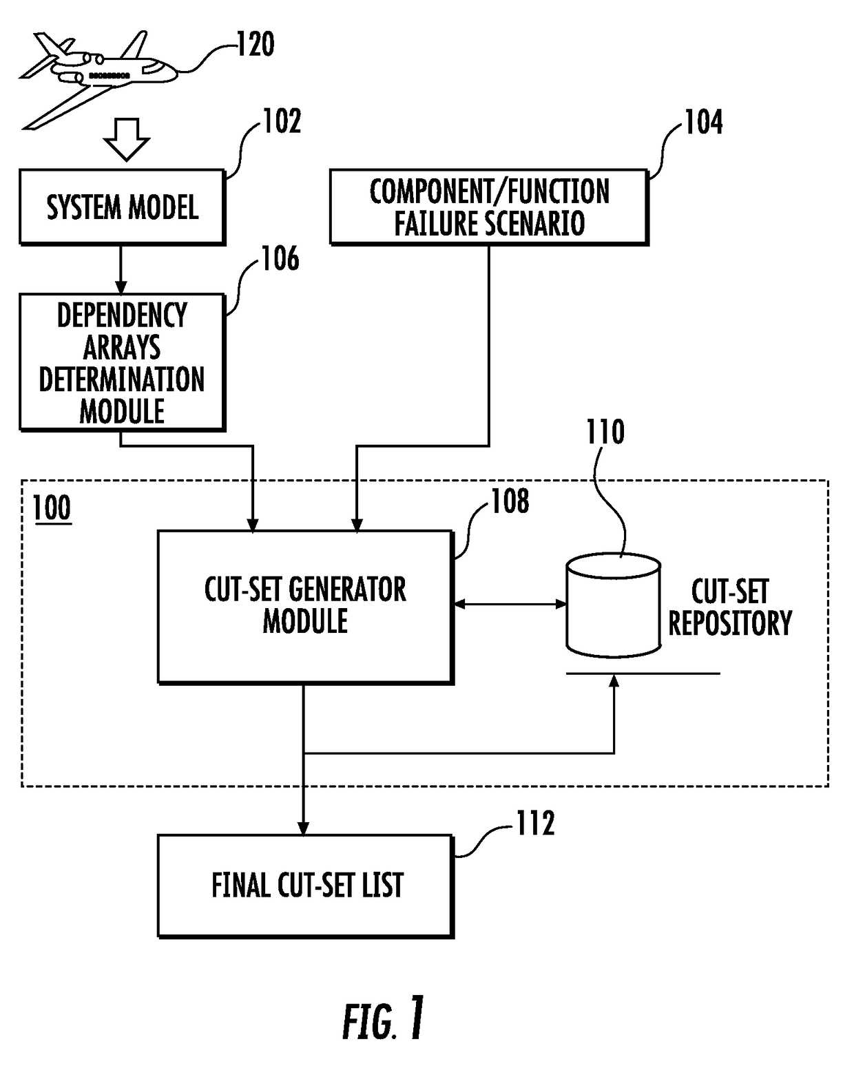
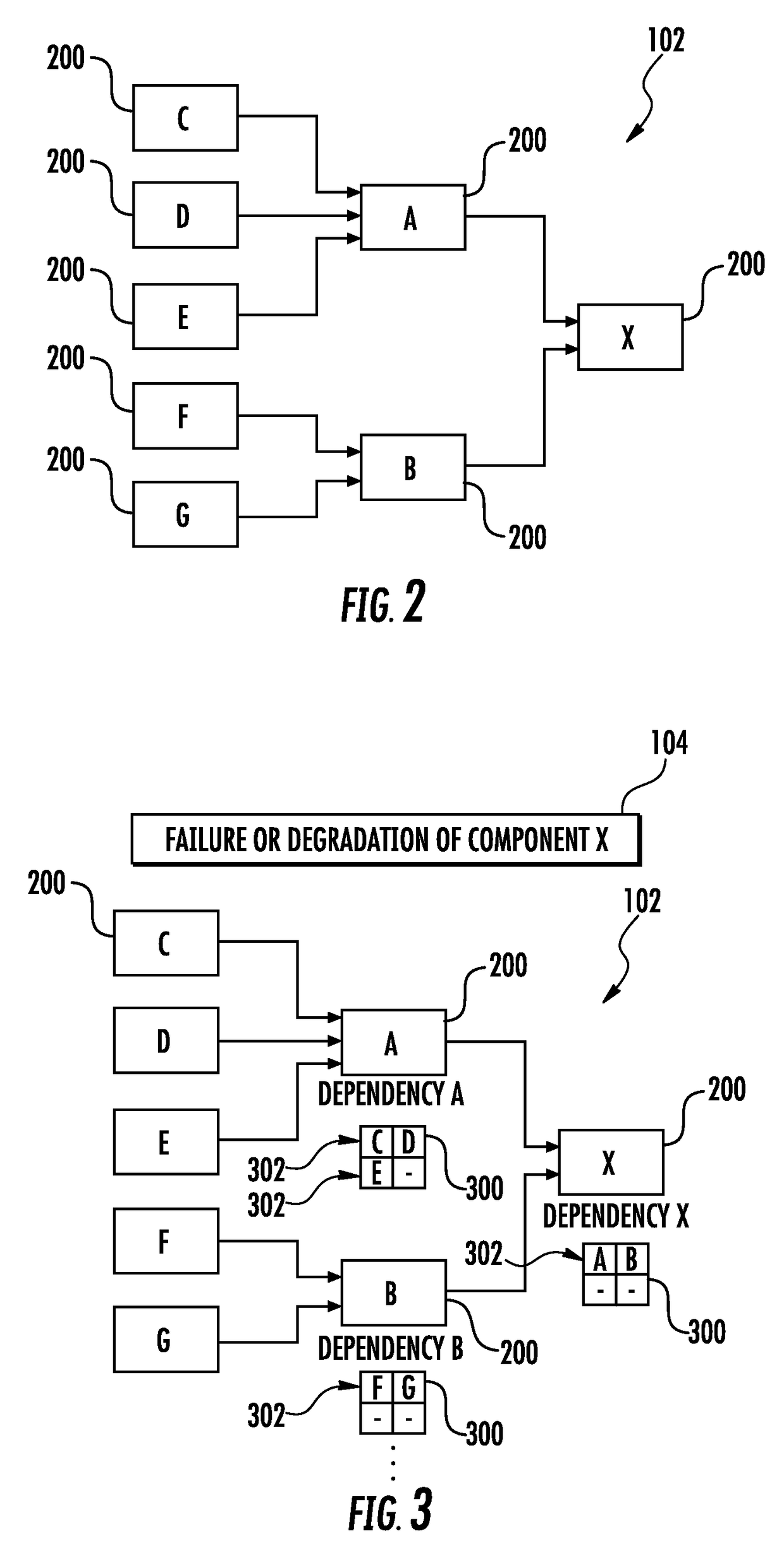
This patent is about a system and method for generating cut-sets in large systems to improve efficiency and accuracy. The system uses a system model to identify components that serve as common resources for a large number of components and groups together components that are re-occurring in several related modes. The system also receives a possible component failure or degradation condition and identifies the upstream scenarios that will cause the condition based on the dependencies described in the model. The result is a dependency matrix for the component analyzed based on upstream components. Overall, this system can quickly and efficiently compute minimal cut-sets in highly integrated, large systems, which is useful for system reliability assessment and design assurance activities.

Problems solved by technology

However, the cut-set generation process can be time consuming when applied to large systems made of a great number of components.
Most of the existing solutions for system reliability assessment make use of Fault Tree Analysis (FTA), a method which is time consuming.
This method is still time consuming for large systems.
Moreover, each condition can have a large number of potential causes (e.g., cut-sets), containing single or typically multiple component reliability issues.

Method used


Image

  • Method and system for generating minimal cut-sets for highly integrated large systems
  • Method and system for generating minimal cut-sets for highly integrated large systems
  • Method and system for generating minimal cut-sets for highly integrated large systems

Examples


Embodiment Construction

[0040]Some implementations of the present disclosure will now be described more fully hereinafter with reference to the accompanying drawings, in which some, but not all implementations of the disclosure are shown. Indeed, various implementations of the disclosure may be embodied in many different forms and should not be construed as limited to the implementations set forth herein; rather, these example implementations are provided so that this disclosure will be thorough and complete, and will fully convey the scope of the disclosure to those skilled in the art. For example, unless otherwise indicated, reference something as being a first, second or the like should not be construed to imply a particular order. Also, something may be described as being above something else (unless otherwise indicated) may instead be below, and vice versa; and similarly, something described as being to the left of something else may instead be to the right, and vice versa. Like reference numerals ref...


PUM


Abstract

A system and method are provided for generating minimal cut-sets for highly integrated large systems. The method includes receiving a system model (102) and a scenario (104), and obtaining a dependency array (300) from the system model (102) according to the scenario, with the dependency array (300) including at least one case (302). The method includes selecting a case (302) in the dependency array (300). The method includes querying a cut-set repository (110) to determine if a cut-set for a component (200) in the case (302) is already stored, and retrieving said cut-set; and if a cut-set is not stored, generating the minimal cut-set for the component (200). And the method includes computing a final cut-set list (112) by expanding the dependency array (300) using the cut-set for the component (200). The method improves the efficiency of cut-set generation applied to manufactured systems with great number of components.

Description

CROSS-REFERENCE TO RELATED APPLICATION(S)[0001]The present application claims priority to European Patent Application No. EP15382581.5, entitled: Method and System for Generating Minimal Cut-Sets for Highly Integrated Large Systems, filed Nov. 24, 2015, the content of which is incorporated by reference in its entirety.TECHNOLOGICAL FIELD[0002]The present disclosure is comprised in the field of reliability assessment in systems comprising a large number of components, such as a part or function of an airplane. More specifically, the disclosure relates to methods for generation of minimal cut-sets in highly integrated large systems.BACKGROUND[0003]A cut-set is a collection of possible functional sub-component failures or degradations that could lead to a possible failure event or degradation of a higher-level component or function. Cut-set analysis can be applied to any system such as automobiles or airplanes to identify and rank system dependencies during the design phase. In particu...

Claims


Application Information

Patent Timeline
Patent Type & Authority Applications(United States)
IPC IPC(8): G05B19/418
CPCG05B2219/39159G05B19/4188G05B23/0248G05B23/0251G06Q10/20
Inventor SWEENEY, STEPHENFUCKE, LARS
Owner THE BOEING CO
Learn More