Eureka AIR delivers breakthrough ideas for toughest innovation challenges, trusted by R&D personnel around the world.

Radio-frequency module and communication device

a radio-frequency module and communication device technology, applied in the field of radio-frequency modules and communication devices, can solve the problems of increasing the mounting density of components on the radio-frequency front-end modules, the circuit configuration of the radio-frequency modules is becoming more complicated, and the transmission characteristics of the radio-frequency modules are secured. the effect of improving the transmission characteristics

Active Publication Date: 2017-05-18
MURATA MFG CO LTD
View PDF7 Cites 15 Cited by
  • Summary
  • Abstract
  • Description
  • Claims
  • Application Information

AI Technical Summary

Benefits of technology

The patent describes a radio-frequency module that can improve its ability to transmit data while supporting multiple communication bands. This means that the module can work more effectively and efficiently, allowing for smoother and more reliable communication.

Problems solved by technology

In accordance with a reduced size and a more demanding specification of communication devices such as smartphones, a radio-frequency module, such as a radio-frequency front-end module, used in a communication device is becoming increasingly complicated.
For example, the mounting density of components on a radio-frequency module is becoming higher and the circuit configuration of a radio-frequency module is becoming more complicated.
However, as the mounting density of components increases, it is more difficult to separate a circuit on the input side of the switch and a circuit on the output side thereof from each other.
This makes it more difficult to obtain desired transmission characteristics.

Method used


Image

  • Radio-frequency module and communication device
  • Radio-frequency module and communication device
  • Radio-frequency module and communication device

Examples


first preferred embodiment

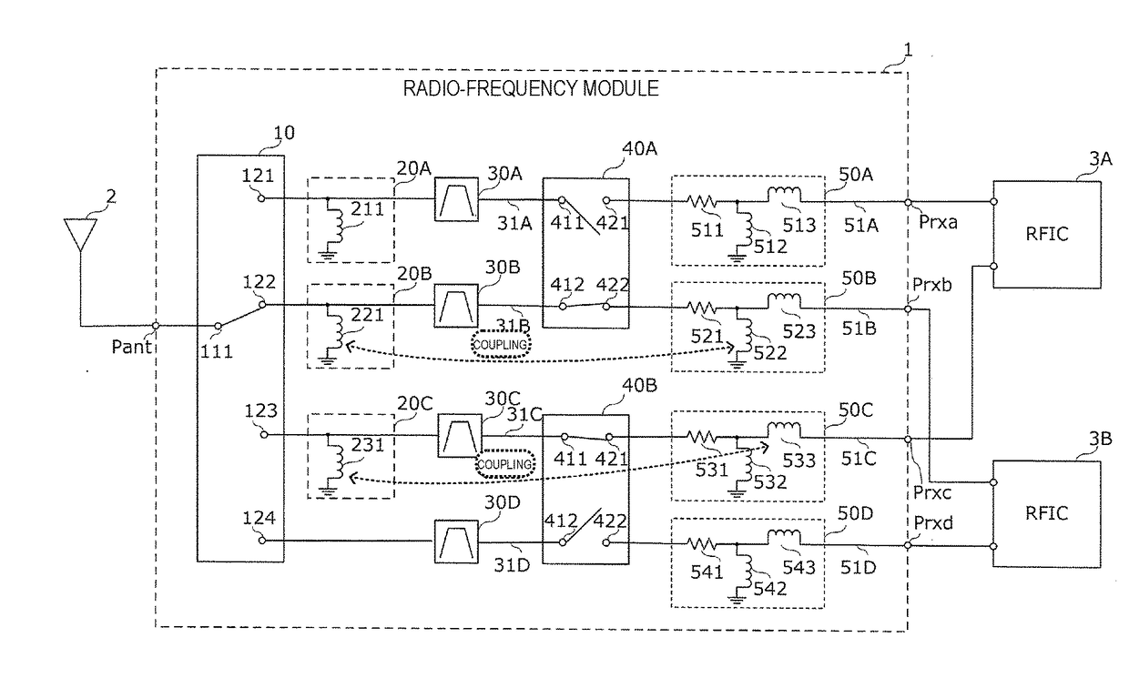
[0049]A radio-frequency module according to a first preferred embodiment of the present invention transmits or receives radio-frequency signals of multiple frequency bands. Such a radio-frequency module is provided, for example, in a front-end portion of a multiband-support cellular phone which is compliant with communication standards such as LTE (Long Term Evolution), and propagates radio-frequency signals of multiple frequency bands between an antenna and an RFIC.

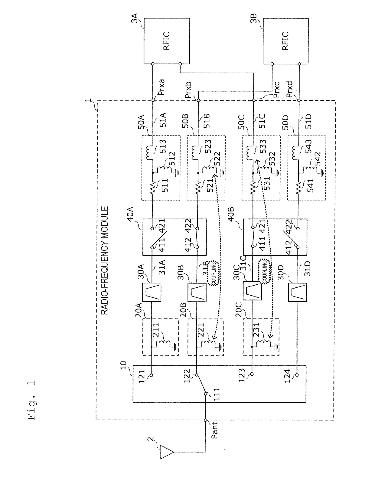
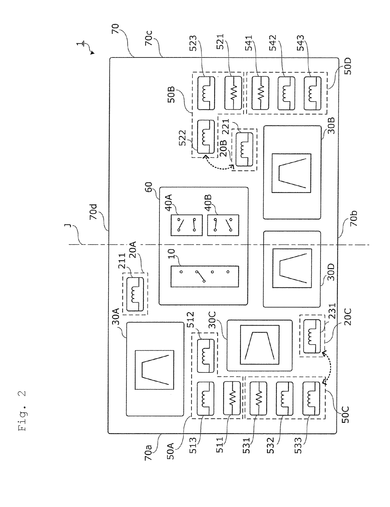
[0050]FIG. 1 is a circuit diagram illustrating an example of the circuit configuration of a radio-frequency module 1 according to the first preferred embodiment of the present invention. In FIG. 1, an antenna 2 and RFICs 3A and 3B to which the radio-frequency module 1 is connected are also shown. A common matching circuit, such as an inductor, may be disposed between the radio-frequency module 1 and the antenna 2, but it is not shown in FIG. 1. In FIG. 1, electromagnetic coupling of components included in the radio-frequ...

second preferred embodiment

[0158]In a second preferred embodiment of the present invention, a communication device including the above-described radio-frequency module will be described below through illustration of a cellular phone.

[0159]FIG. 7 is a plan view schematically illustrating a cellular phone 100 according to the second preferred embodiment of the present invention.

[0160]The cellular phone 100 shown in FIG. 7 is a communication device including the RFICs 3A and 3B and the radio-frequency module 1 of the first preferred embodiment of the present invention. The RFICs 3A and 3B and the radio-frequency module 1 are preferably mounted on the same mother substrate 5 and stored within a casing of the cellular phone 100. At least one of the RFICs 3A and 3B and the radio-frequency module 1 may be mounted on another substrate different from the mother substrate 5.

[0161]According to the second preferred embodiment of the present invention, like the cellular phone 100 including the above-described radio-freque...


PUM


Abstract

A radio-frequency module includes switch elements, first signal paths, band pass filters, first matching circuits, second signal paths, and second matching circuits. Each of the first signal paths is connected between one end of a corresponding one of the switch elements and an antenna terminal. Each of the band pass filters is connected to a corresponding one of the first signal paths and allows a radio-frequency signal of one of the plurality of frequency bands to pass therethrough. Each of the first matching circuits is connected to a corresponding one of the first signal paths. Each of the second signal paths is connected to a corresponding one of the switch elements. Each of the second matching circuits is connected to a corresponding one of the second signal paths. A component included in the first matching circuits and a component included in the second matching circuits are electromagnetically coupled.

Description

CROSS REFERENCE TO RELATED APPLICATIONS[0001]This application claims the benefit of priority to Japanese Patent Application 2015-226096 filed on Nov. 18, 2015. The entire contents of this application are hereby incorporated herein by reference.BACKGROUND OF THE INVENTION[0002]1. Field of the Invention[0003]The present invention relates to a radio-frequency module disposed between a radio-frequency integrated circuit (RFIC) which performs signal processing on radio-frequency signals of different multiple frequency bands and an antenna which transmits or receives radio-frequency signals, and also to a communication device including the radio-frequency module.[0004]2. Description of the Related Art[0005]In accordance with a reduced size and a more demanding specification of communication devices such as smartphones, a radio-frequency module, such as a radio-frequency front-end module, used in a communication device is becoming increasingly complicated. For example, the mounting density...

Claims


Application Information

Patent Timeline
Patent Type & Authority Applications(United States)
IPC IPC(8): H04B1/00H03H7/46H03H9/54H03H7/01H03H7/38H03H9/64
CPCH04B1/006H03H7/38H03H7/46H03H9/54H03H7/0115H03H9/64H03H9/70H03H2250/00
Inventor WATANABE, TAKASHI
Owner MURATA MFG CO LTD
Why Eureka
Eureka Blog
Learn More