Wall And Floor Structure For Reducing Inter-Floor Noise

a technology of inter-floor noise and wall and floor structure, which is applied in the direction of flooring, electrical transducers, instruments, etc., can solve the problems of difficult reduction, conflict deepening, and many floor noise problems, so as to effectively reduce the sound of light and heavy impact, the effect of effective reduction of floor nois

Active Publication Date: 2017-05-18
KOREA ADVANCED INST OF SCI & TECH
View PDF10 Cites 0 Cited by
  • Summary
  • Abstract
  • Description
  • Claims
  • Application Information

AI Technical Summary

Benefits of technology

[0039]Therefore, the hard panel of the wall and floor structures according to example embodiments may effectively reduce the light and heavy impact sounds.
[0040]In addition, the hard panel may be formed by at least one patterned layer to refract and reflect the acoustic wave such that the floor noise may be effectively dissipated.
[0041]The hard panel may further include the sound absorbing material to absorb the noise passing through the hard panel such that the floor noise may be effectively reduced.
[0042]The hard panel may be applied to existing buildings, and thus installation costs may be reduced.
[0043]Construction costs may be saved by the low cost of the hard panel.

Problems solved by technology

Therefore, there are many floor noise problems and conflicts are deepening and being raised as social issues.
The heavy impact sound has physical characteristics that impact force is large and acoustic duration is long, and it is difficult to reduce it.
However, the column type structure model is relatively expensive, and it is applied only to newly built houses, so measures against existing apartments are necessary.
Since the flooring materials are closely related to heating, the building material disclosed in the patent document 1 formed of the aerogel having high heat insulation is not suitable as the flooring material.
In addition, aerogel is put between the cardboards having many fine pores, and the aerogel is an expensive material.
Therefore the building material disclosed in the patent document 1 is not suitable as a flooring material for flooring for soundproof purposes.

Method used


Image

  • Wall And Floor Structure For Reducing Inter-Floor Noise
  • Wall And Floor Structure For Reducing Inter-Floor Noise
  • Wall And Floor Structure For Reducing Inter-Floor Noise

Examples


embodiment 1

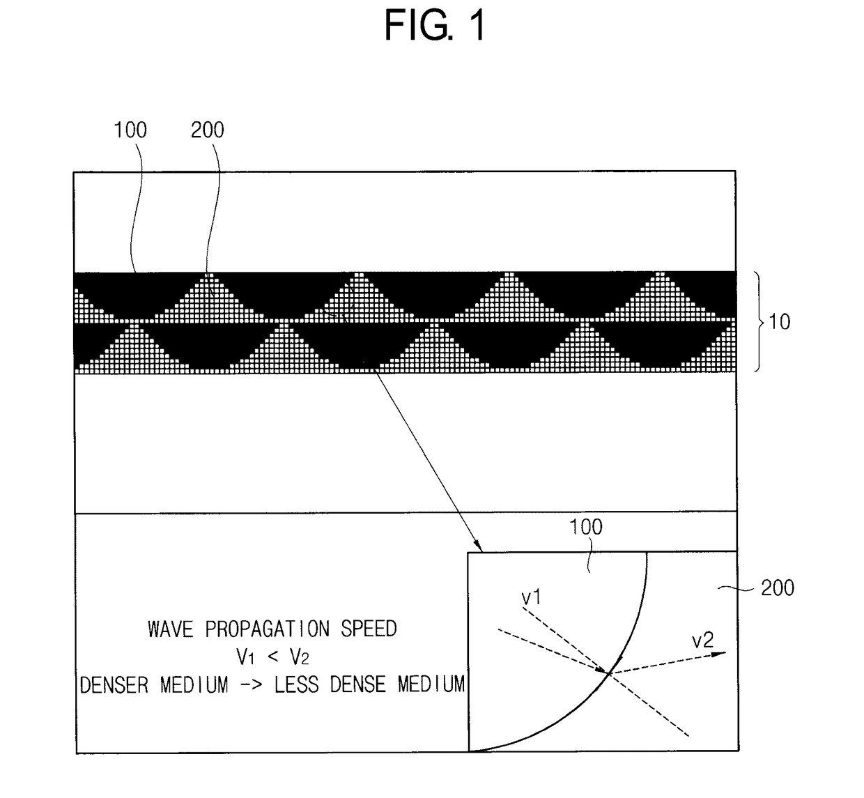
[0089]In some embodiments, a material of the patterned layer 100 may be substantially the same as the base layer 200 and least one of density and elastic modulus of the patterned layer 100 may be different from the base layer 200.

[0090]FIG. 7 is a cross-sectional view of a hard panel including a patterned layer having substantially the same material as a base layer. Material property of the patterned layer 100 may be different from the base layer 200. In some embodiments, a density and an elastic modulus of the patterned layer 100 may be different from the base layer 200. The hard panel 10 may horizontally transmit an acoustic wave WS from an upper side of the hard panel 10. In FIG. 7 (as illustrated at (a) of FIG. 7), the acoustic wave WS may move from the denser medium 320 to the less dense medium 310. In FIG. 7 (as illustrated at (b) of FIG. 7), the acoustic wave WS may move from the less dense medium 310 to the denser medium 320.

[0091]FIG. 8 is a schematic diagram illustrating a...

embodiment 2

[0095]In some embodiments, a material of the patterned layer 100 of the hard panel 10 may be different from the base layer 200.

[0096]FIG. 10 is a cross-sectional view of the hard panel including the patterned layer having different material from the base layer. The material, a density, and an elastic modulus of the patterned layer may be different from the base layer. The hard panel 10 may horizontally transmit an acoustic wave WS from an upper side of the hard panel 10 by the Snell's law. In FIG. 10 (as illustrated at (a) of FIG. 10), the acoustic wave WS may move from the denser medium 320 to the less dense medium 310. In FIG. 10 (as illustrated at (b) of FIG. 10), the acoustic wave WS may move from the less dense medium 310 to the denser medium 320.

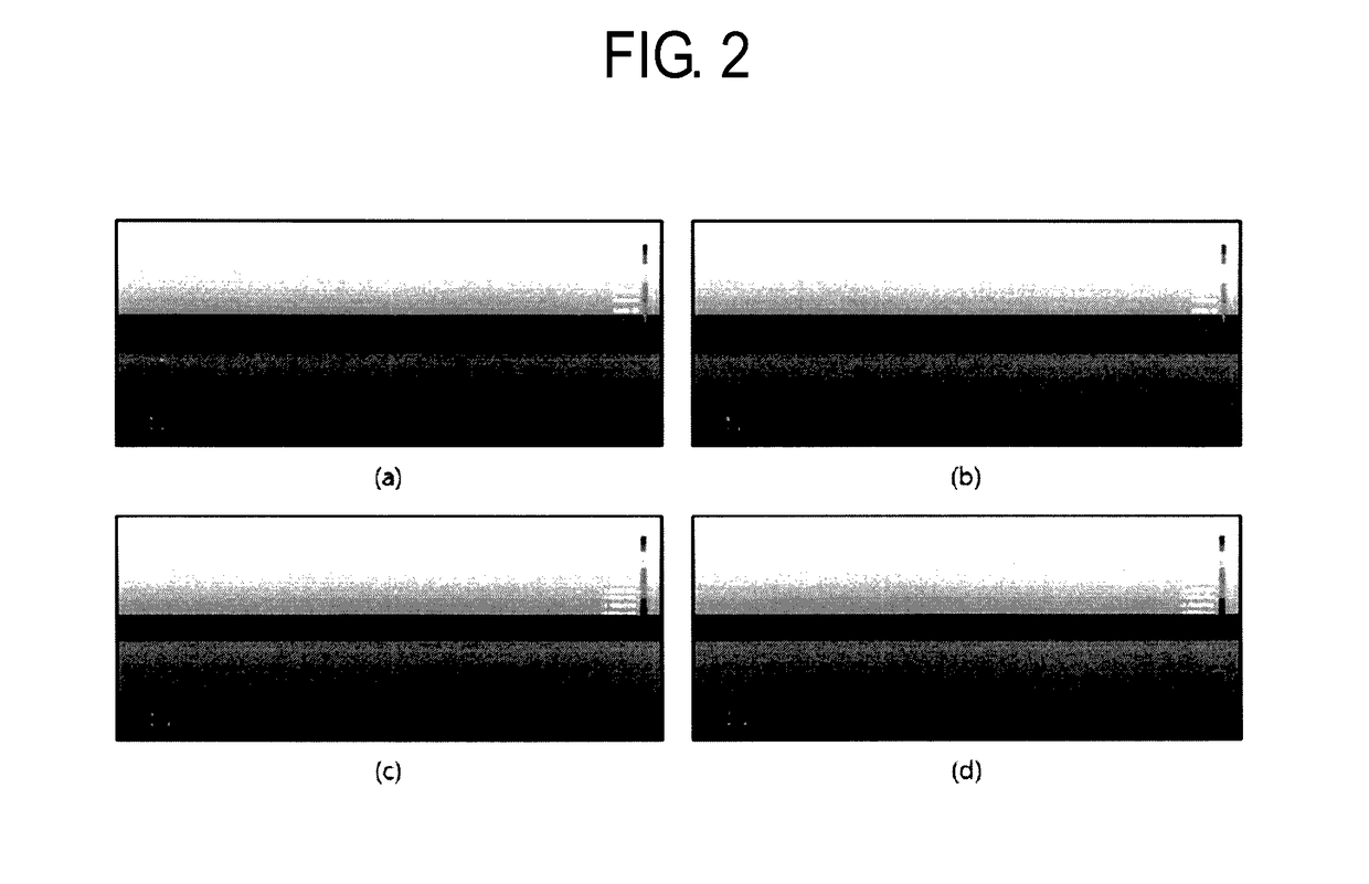
[0097]FIG. 11 is a schematic diagram illustrating a down scale model of the hard panel of FIG. 10. In FIG. 11, FIG. 11 (a) shows a schematic diagram of the down scale model experiment. In FIG. 11, FIG. 11 (b) shows an actual setting fo...

embodiment 3

[0100]In some embodiments, the patterned layer 100 in the hard panel 10 may be a single layer or multi layers.

[0101]FIG. 13 is a cross-sectional view of a hard panel including a plurality of patterned layers according to example embodiments. FIG. 14 is a cross-sectional view of a hard panel including a single patterned layer according to example embodiments.

[0102]Simulation conditions of the hard panel having multi-layered patterns of FIG. 13 are shown in Table 4.

Dynamic elastic MaterialDensity (g / cm3)modulus (GPa)Medium 1PVC1.262.8Medium 2ABS1.509.8

[0103]Semicircle patterns may be formed in the plurality of layers. A thickness of the hard panel 10 is about 1 cm.

[0104]Simulation conditions of the hard panel having a single layer pattern of FIG. 14 are shown in Table 5.

Dynamic elastic MaterialDensity (g / cm3)modulus (GPa)Medium 1PVC1.262.8Medium 2ABS1.509.8

[0105]Semicircle patterns may be formed in the single layer.

[0106]The hard panel having the single layer pattern may be more effec...


PUM


Abstract

A hard panel of wall and floor structures for reducing floor impact sound according to example embodiments includes patterned layer having different density and elastic modulus form a base layer. A transmission path of an acoustic wave may be changed in a lateral direction by passing the patterned layer and the sound energy is dissipated by the refection, refraction, and cancellation of the acoustic wave. Thus, a noise is reduced.
The hard panel of the wall and floor structures according to example embodiments is effectively reduces the light and heavy impact sounds. In addition, the hard panel is formed by at least one patterned layer to refract and reflect the acoustic wave such that the floor noise may be effectively dissipated. The hard panel is further includes the sound absorbing material to absorb the noise passing through the hard panel such that the floor noise can be effectively reduced.

Description

BACKGROUND[0001]1. Field[0002]Example embodiments of the inventive concept relate to wall and floor structures for reducing floor impact sound. More particularly, example embodiments of the inventive concept relate to techniques for reducing floor impact sound in the wall and floor structures by changing a direction of an acoustic wave and dissipating sound energy with a panel having a patterned layer formed using materials having different densities and elastic modulus.[0003]2. Discussion of Related Art[0004]Because of the rapid urbanization, the majority of people live in apartment houses. Therefore, there are many floor noise problems and conflicts are deepening and being raised as social issues.[0005]Floor impact sound of the floor noises is divided into a light impact sound and a heavy impact sound according to the impact characteristics. The light impact sound is an upper register sound of 58bB or less with a light and hard sound, such as dragging a table, garlic clenching, fa...

Claims


Application Information

Patent Timeline
Patent Type & Authority Applications(United States)
IPC IPC(8): E04B1/86G10K11/168E04F13/075E04B5/16E04F15/20
CPCE04B1/86E04B5/16E04B2001/8263E04F13/075G10K11/168E04F15/20E04F15/203H04R1/345
Inventor HONG, JUNG-WUKYANG, SEUNG-JINLEE, SANG-EON
Owner KOREA ADVANCED INST OF SCI & TECH
Why Eureka
Try Eureka