Resonance circuit complex electronic component and resonance circuit device

Active Publication Date: 2017-05-04
MURATA MFG CO LTD
View PDF2 Cites 1 Cited by
  • Summary
  • Abstract
  • Description
  • Claims
  • Application Information

AI Technical Summary

Benefits of technology

The invention provides a small but effective electronic component that helps prevent parts from becoming worn down while using a compact device. This component can be used in a resonance circuit device.

Problems solved by technology

This causes an increase in the size of the surface acoustic wave device, that is, the resonance circuit device.

Method used


Image

  • Resonance circuit complex electronic component and resonance circuit device
  • Resonance circuit complex electronic component and resonance circuit device
  • Resonance circuit complex electronic component and resonance circuit device

Examples


Embodiment Construction

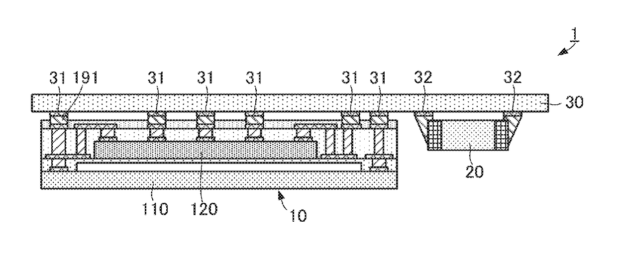
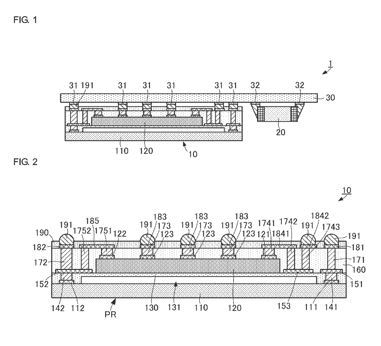
[0039]A resonance circuit complex electronic component and a resonance circuit device according to a first preferred embodiment of the present invention will be described with reference to the drawings. FIG. 1 is a side view showing the resonance circuit complex electronic component and the resonance circuit device according to the first preferred embodiment of the present invention. FIG. 2 is a side view of the resonance circuit complex electronic component according to the first preferred embodiment of the present invention. FIGS. 1 and 2 show a side section of the resonance circuit complex electronic component.

[0040]As shown in FIG. 1, a resonance circuit device 1 includes a resonance circuit complex electronic component 10, a surface mount inductor element 20, and a board 30. The board 30 is a mounting board including mounting lands 31 and 32 provided therein. The mounting land 31 is a land conductor on which the resonance circuit complex electronic component 10 is mounted. The ...


PUM


Abstract

A resonance circuit complex electronic component includes a first circuit element and a second circuit element defining a resonance circuit, an external connection terminal connected to outside, and a plurality of routing conductors connecting an external terminal of the first circuit element and an external terminal of the second circuit element to the external connection terminal, respectively. At least one of the plurality of routing conductors includes an inductor conductor extending in a direction not in parallel with a mounting surface.

Description

CROSS REFERENCE TO RELATED APPLICATIONS[0001]This application claims the benefit of priority to Japanese Patent Application 2014-124910 filed on Jun. 18, 2014 and is a Continuation Application of PCT / JP2015 / 067409 filed on Jun. 17, 2015. The entire contents of each application are hereby incorporated herein by reference.BACKGROUND OF THE INVENTION[0002]1. Field of the Invention[0003]The present invention relates to a resonance circuit complex electronic component preferably for use in a resonance circuit, and a resonance circuit device.[0004]2. Description of the Related Art[0005]Various types of resonance circuit devices have been conventionally known in which various electronic components are disposed in a dielectric board so as to define a resonance circuit. For example, as one type of the resonance circuit devices, Japanese Unexamined Patent Application Publication No. 2002-232259 describes a surface acoustic wave device including a surface acoustic wave element, an inductor, a ...

Claims


Application Information

Patent Timeline
IPC IPC(8): H03H9/54H03H9/205H03H1/00
CPCH03H9/542H03H1/0007H03H2210/025H03H2001/0021H03H9/205H03H7/01H03H9/17H03H9/25H03H9/0542H03H9/0552H03H9/059H03H9/566H03H9/64H01L25/00H01L2924/0002H01L2224/19H01L2224/04105H01L2224/12105H01L2224/32145H01L2924/00
Inventor IWAMOTO, TAKASHI
Owner MURATA MFG CO LTD
Why Eureka
Try Eureka