
Spark plug

a spark plug and spark plug technology, applied in spark plugs, sparking devices, basic electric elements, etc., can solve the problems of insufficient investigation of measures to suppress the growth of oxide scale at the interface between the precious metal tip and the electrode base material, and the probability of cracking in the relatively low strength of the oxide scale, so as to suppress the formation of oxide scale, improve the reliability of the joint between the precious metal tip and the electrode base material, and suppress the occurrence of cracks.

Active Publication Date: 2017-05-04
NGK SPARK PLUG CO LTD
View PDF0 Cites 7 Cited by
  • Summary
  • Abstract
  • Description
  • Claims
  • Application Information

AI Technical Summary

Benefits of technology

The present invention provides a spark plug with improved reliability. This is achieved by reducing the growth of oxide scale at the interface between the precious metal tip and the melt portion. This is achieved by keeping the distance between the precious metal tip and the melt portion equal to or greater than 0.110 mm. By doing this, growth of the oxide scale is prevented and the joint between the precious metal tip and the electrode base material can be further improved.

Problems solved by technology

Therefore, when a stress occurs as described above, crack is likely to occur in the oxide scale having the relatively low strength.
The growth of the oxide scale toward the inside of the melt portion interface causes the crack to extend toward the inside of the melt portion interface, leading to falling off of the precious metal tip, which makes it difficult to secure reliability of the joint between the precious metal tip and the electrode base material.
However, measures to suppress growth of the oxide scale at the interface between the precious metal tip and the electrode base material have not been sufficiently investigated.

Method used


Image

  • Spark plug
  • Spark plug
  • Spark plug

Examples


modification 2 (

Modification of Welding Method):

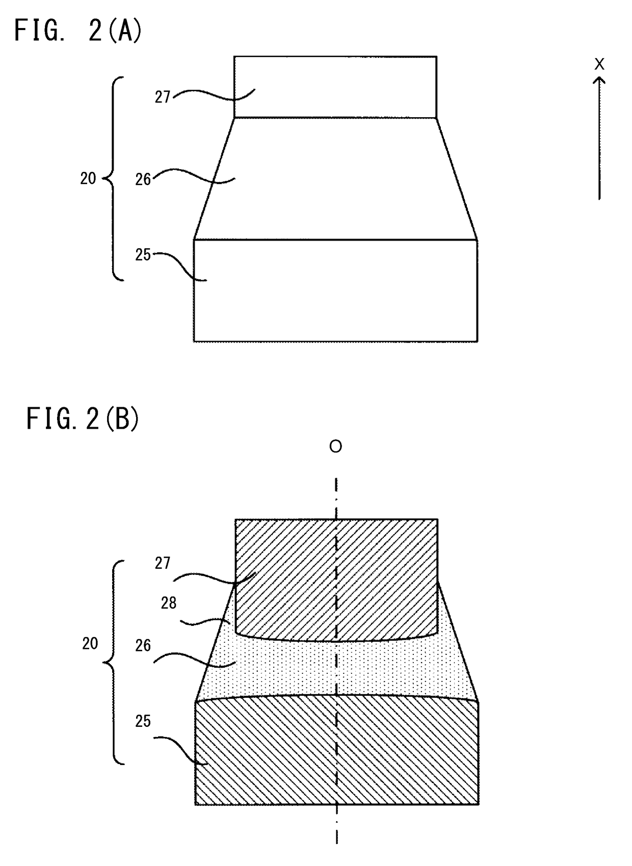
[0050]Welding of the precious metal tip 27 and the electrode base material 25 may be performed by other welding methods than the above-described laser welding, such as electron beam welding. In this case, as long as the electron beam welding is capable of melting the precious metal tip 27 and the electrode base material 25 by irradiating the precious metal tip 27 with an energy beam, from the outer peripheral side thereof toward the inside thereof, and welding them together to form the melt portion 26 having the melt sag 28, the present invention can be applied to the electron beam welding as in the above embodiment.

modification 3 (

Modification of Electrode):

[0051]In the above embodiment, the length, in the direction of the center axis O, of the melt sag 28 formed by welding the precious metal tip 27 to the electrode base material 25 of the center electrode 20 is defined. However, another configuration may be adopted. The present invention may be applied to the ground electrode 30 instead of or in addition to the center electrode 20.

examples

[0052]Various precious metal tips 27 having different components and sizes were welded to the electrode base material 25, thereby manufacturing a plurality of electrodes having different lengths of the melt sag 28 in the direction of the center axis O. A thermal test was performed to expose these electrodes to heating and cooling cycles, and the degree of the oxide scale formed at the interface between each precious metal tip 27 and the melt portion 26 was examined. Regarding the thermal test, two types of tests (a first thermal test and a second thermal test) having different heating conditions were performed. The thermal test was performed as a desk test in which the precious metal tips were welded onto a welding base material imitating the electrode base material 25 and heated by using a burner, instead of actually fabricating a spark plug and actually performing ignition operation using the spark plug.

[Electrodes for Test]

[0053]FIG. 4 is an explanatory view showing the specs of ...


PUM

PropertyMeasurementUnit
distanceaaaaaaaaaa
distancesaaaaaaaaaa
voltageaaaaaaaaaa

Abstract

A spark plug including an electrode having a cylindrical precious metal tip welded thereto, the electrode having a melt portion in which the precious metal tip and the electrode base material are melted, wherein the melt portion includes a melt sag over an entire circumference on a side surface of the precious metal tip.

Description

FIELD OF THE INVENTION[0001]The present invention relates to spark plugs.BACKGROUND OF THE INVENTION[0002]As a conventional spark plug, a spark plug has been known which includes an electrode (a center electrode or a ground electrode) to which an electrode tip (hereinafter referred to as “precious metal tip”) formed of a precious metal or an alloy containing a precious metal as a main component is joined (see Japanese Patent Application Laid-Open (kokai) No. 2013-178912, for example). Generally, a precious metal tip is joined to an electrode base material by laser welding. Specifically, the precious metal tip is irradiated with a laser beam along its outer periphery, whereby the precious metal tip is joined to the electrode base material. When the precious metal tip is welded to the electrode base material, usually, a melt portion in which the material of the precious metal tip and the material of the electrode base material are melted is formed between the precious metal tip and th...

Claims


Application Information

Patent Timeline
Patent Type & Authority Applications(United States)
IPC IPC(8): H01T13/39H01T13/32
CPCH01T13/32H01T13/39H01T13/20
Inventor SUZUKI, KAORI
Owner NGK SPARK PLUG CO LTD
Learn More