Nmr-mas turbine assembly

a technology of mas turbine and mas turbine, which is applied in the direction of mechanical equipment, magnetic measurements, instruments, etc., can solve the problems of reducing the significance of mas turbine, reducing the nmr spectra, and making evaluation of mas more difficul

Active Publication Date: 2017-04-20
BRUKER BIOSPIN
View PDF0 Cites 3 Cited by
  • Summary
  • Abstract
  • Description
  • Claims
  • Application Information

AI Technical Summary

Benefits of technology

The invention is a turbine cap that can rotate at high speeds, up to 111 kHz. It is easy to make and has been tested with an NMR-MAS rotor, showing good running stability. The turbine cap has a second ventilation slot that helps to dissipate the compressed gas and improve its discharge. This reduces the risk of interacting compressed gas flows in the region of the drive nozzle system. Overall, the invention improves the performance of the turbine cap and makes it easier to achieve high rotation speeds.

Problems solved by technology

In solid samples, anisotropic interactions (in particular dipolar interactions and quadrupolar interactions as well as the anisotropic portion of the chemical shift) of the atomic nuclei lead to line broadening in the NMR spectra which reduces their significance and makes evaluation thereof more difficult.
At higher speeds of rotation of the MAS rotor, it becomes increasingly difficult to ensure adequate running stability.
On the one hand, a small size of an MAS rotor, in particular a small outside diameter, is troublesome to produce.
Known MAS rotors are not generally suitable for operation at higher rotation frequencies, for example of 100 kHz or more, in particular on account of too high tangential speeds.
Scaling down conventional MAS rotors usually results in significant production difficulties or the MAS rotor does not run sufficiently stably.
Finally, it is often simply impossible to find a suitable turbine cap, in particular a blade geometry, with which the required rotation frequency of the MAS rotor can be achieved.

Method used


Image

  • Nmr-mas turbine assembly
  • Nmr-mas turbine assembly
  • Nmr-mas turbine assembly

Examples


Embodiment Construction

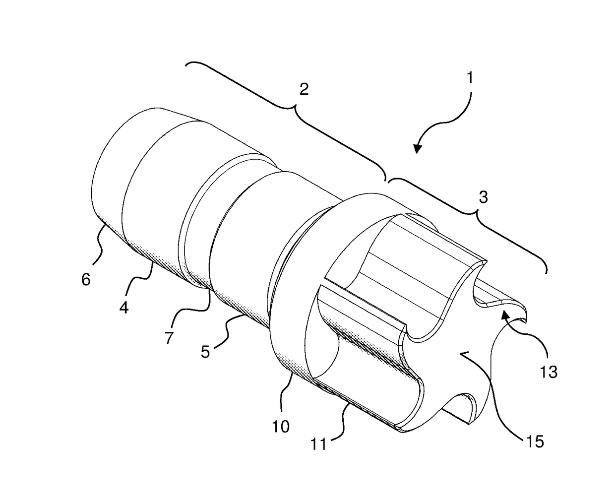
[0056]The present invention introduces a turbine cap for an NMR-MAS rotor, an associated NMR-MAS rotor having such a turbine cap and an NMR-MAS stator for the NMR-MAS rotor. Here, turbine, MAS rotor, and MAS stator are designed and adjusted to one another for an outside diameter of the rotor tube between 0.675 mm and 0.725 mm, in particular of 0.700 mm ±0.005 mm. The invention enables for the first time to rotate a solid sample at frequencies of up to 111 kHz and, as a result, to correspondingly reduce line broadening due to anisotropic effects in NMR measurements as part of a rotation below the so-called “magic angle” (magic angle spinning, MAS).

Turbine Cap

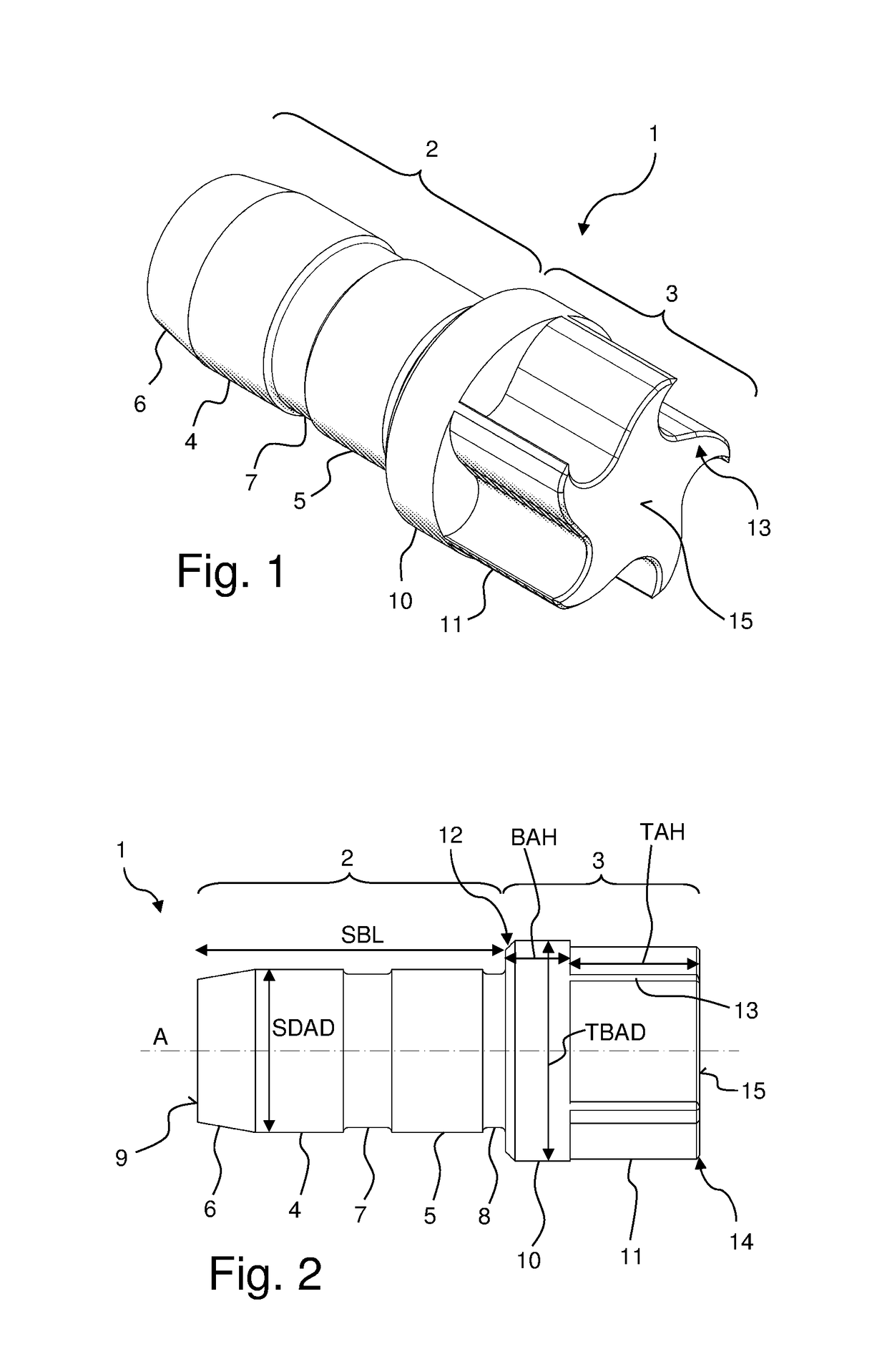
[0057]FIG. 1 shows an exemplary embodiment of a turbine cap 1 according to the invention in a schematic oblique view; FIG. 2 shows this turbine cap 1 in a schematic side view. The turbine cap 1 is made from polyamide and has a stopper region 2 and a turbine region 3. The stopper region 2 has a first sealing section 4 and a second...


PUM


Abstract

A nuclear magnetic resonance-magic angle spinning (NMR-MAS) turbine assembly has a MAS rotor with turbine cap having a stopper region and a turbine region. The stopper region allows feeding into a rotor tube and has at least one sealing section for resting against an inner wall of the rotor tube. The turbine region has a collar section for resting against a face side of the rotor tube and a turbine section that forms the turbine blades, which protrude axially from the collar section without extending radially further than the collar section. The arrangement of the rotor allows for very high rotation frequencies that, correspondingly, reduce line broadening in NMR measurements.

Description

BACKGROUND OF THE INVENTION[0001]Field of the Invention[0002]The invention relates generally to an NMR-MAS turbine assembly and, more specifically, to a turbine cap for an NMR-MAS rotor.[0003]Description of the Related Art[0004]An example of an NMR-MAS turbine cap is described in U.S. Pat. No. 8,436,616 B2. Nuclear magnetic resonance (NMR) spectroscopy is a powerful method of instrumental analysis based on the alignment of nuclear spins in a strong magnetic field and their behavior when radiated with high-frequency pulses. The respective chemical environment of the nuclei leads to characteristic changes in the resonant frequencies of the nuclei, thus enabling conclusions relating to their chemical composition to be drawn from NMR spectra of samples.[0005]In solid samples, anisotropic interactions (in particular dipolar interactions and quadrupolar interactions as well as the anisotropic portion of the chemical shift) of the atomic nuclei lead to line broadening in the NMR spectra wh...

Claims


Application Information

Patent Timeline
Patent Type & Authority Applications(United States)
IPC IPC(8): G01R33/30F01D25/16F01D9/02F01D5/02F01D5/14
CPCG01R33/307F01D5/02F01D5/141F05D2250/141F01D25/16F05D2250/711F01D9/02
Inventor OSEN, DAVIDKNOTT, BENNO
Owner BRUKER BIOSPIN
Why Eureka
Try Eureka