Control circuit for switching power supply device, and switching power supply device

a control circuit and power supply technology, applied in the direction of power conversion systems, dc-dc conversion, instruments, etc., can solve problems such as difficulty in doing, and achieve the effects of maximizing the conducted emi noise reduction effect, simple configuration, and increasing the performance of an emi filter

Active Publication Date: 2017-04-06
FUJI ELECTRIC CO LTD
View PDF3 Cites 11 Cited by
  • Summary
  • Abstract
  • Description
  • Claims
  • Application Information

AI Technical Summary

Benefits of technology

[0024]The control circuit for a switching power supply device and the switching power supply device configured as described above modulate the switching signal from the oscillation circuit using the Hershey's Kiss approximation signal, and thus have an advantage of maximizing a conducted EMI noise reduction effect while using a simple configuration. It is therefore not necessary to increase the performance of an EMI filter; and even if it is necessary to increase the performance of the EMI filter, the scale of such an increase can be kept to a minimum.

Problems solved by technology

However, using a dedicated IC only for obtaining a Hershey's Kiss waveform, forming a complicated and large-scale Hershey's Kiss waveform generating circuit instead of a triangular waveform generating circuit having a simple configuration in a power supply IC for control, or the like in switching power supply devices is problematic in that in reality, it is difficult to do so.

Method used


Image

  • Control circuit for switching power supply device, and switching power supply device
  • Control circuit for switching power supply device, and switching power supply device
  • Control circuit for switching power supply device, and switching power supply device

Examples


Embodiment Construction

[0033]A case where an embodiment of the present invention is applied in a flyback-type switching power supply device having a small number of components and capable of handling a broad input voltage range will be described in detail hereinafter with reference to the drawings. In the following descriptions, the same reference numerals may be used for both terminal names and for the voltages, currents, signals, and so on at those terminals.

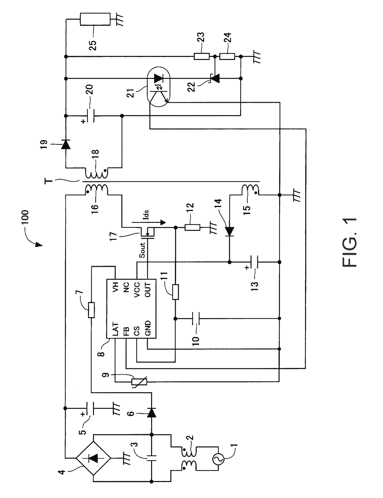
[0034]FIG. 1 is a circuit diagram illustrating a representative example of the configuration of a switching power supply device according to the embodiment.

[0035]This switching power supply device 100 has a control IC 8, which is a control circuit for PWM (Pulse Width Modulation) control, and includes at least a transformer T, a diode 19, a capacitor 20, and a switching element as illustrated in the drawing. Here, a MOSFET (Metal Oxide Semiconductor Field Effect Transistor) 17 is used as the switching element.

[0036]A commercial AC power supply 1 is ...


PUM


Abstract

A conducted EMI noise reduction effect close to that achieved by using an optimal modulating waveform as a modulating wave is achieved when employing a frequency spreading technique as a measure against noise when a conducted EMI standard is extended to a low-frequency range. A triangular wave/Hershey's Kiss approximation signal generating unit and a triangular wave generation control unit generate a fundamental triangular wave by a transistor charging a capacitor with a current and a transistor discharging the current from the capacitor. A slope switching signal generating unit generates signals expressing the start and end of a charge period and the start and end of a discharge period. An additional charge or additional discharge is carried out in response to the signals turning a transistor on, and the slope of the triangular wave temporarily increases in that period only.

Description

BACKGROUND OF THE INVENTION[0001]Technical Field[0002]The present invention relates to a control circuit for a switching power supply device and to a switching power supply device, and particularly relates to a control circuit for a switching power supply device and to a switching power supply device that reduce the occurrence of noise by introducing jitter (frequency spreading) to a switching frequency.[0003]Background Art[0004]A switching power supply device rectifies and smoothes a commercial AC voltage and switches the smoothed voltage using a switching element in order to generate a prescribed DC voltage and output the voltage to a load. When the switching element is switched at a prescribed switching frequency, higher-order harmonics that take the prescribed switching frequency as their fundamental waves are produced at the same time. These higher-order harmonics radiate outside the switching power supply device as radiated EMI (electromagnetic interference) noise and conducte...

Claims


Application Information

Patent Timeline
Patent Type & Authority Applications(United States)
IPC IPC(8): H02M3/335H02M1/36H02M1/08H02M1/44
CPCH02M3/33523H02M1/44H02M2001/0009H02M1/08H02M1/36H02M1/0009
Inventor NISHIJIMA, KENICHI
Owner FUJI ELECTRIC CO LTD
Why Eureka
Try Eureka