
Nanoparticulate encapsulation barrier stack

a technology of encapsulation barrier and nanoparticulate, which is applied in the direction of transportation and packaging, organic semiconductor devices, synthetic resin layered products, etc., can solve the problems of encapsulation technology not keeping pace with oled technology development, rapid deformation of atmospheric conditions, and inability to adapt to applications. , to achieve the effect of reducing the lateral diffusion of oxygen/moistur

Inactive Publication Date: 2017-04-06
AGENCY FOR SCI TECH & RES
View PDF8 Cites 4 Cited by
  • Summary
  • Abstract
  • Description
  • Claims
  • Application Information

AI Technical Summary

Benefits of technology

The invention is based on the discovery that adding a layer of reactive nanoparticles to an inorganic barrier layer can reduce the amount of moisture and oxygen that can pass through the barrier layer. By reacting with the defects in the barrier layer, the nanoparticles plug the holes and improve the performance of the barrier. The use of these nanopartices can also improve the adhesion between barrier layers. The invention can be applied to protect sensitive components from moisture and oxygen, such as electronic devices and drugs, and can be used in the fabrication of OLED displays. The ultra high barrier performance requires a thin layer of sealing with a low defect density.

Problems solved by technology

One commonly known problem with OLED structures and other oxygen and / or moisture sensitive electroluminescent devices is that they degrade rapidly under atmospheric conditions.
However, this approach is not suitable for applications such as OLEDs or solar cells in which opacity is a requirement and the quality of light transmitted through the encapsulation must be maintained.
Recent developments in OLED technology has seen the rise of flexible OLEDs which require that the encapsulation structures are flexible, thereby making it more apparent that encapsulation technology has not kept pace with developments in OLED technology.
However, due to their permeability to moisture and oxygen, encapsulation structures formed from polymers alone are nowadays considered to be inadequate for achieving low permeation rates as the required standard for oxygen and water vapor impermeability are orders of magnitude lower than what is achievable with the best polymer substrates using today's state of the art in industrial polymer technology.
Despite possessing improved barrier properties, it has been found that the performance of inorganic barrier laminates is still limited by inherent structural defects.
Recent studies have shown that structural defects such as pinholes, cracks, grain boundaries, etc., allows oxygen and moisture to permeate over time, leading to poorer than expected barrier performance.
It is difficult to control fabrication to such an extent that defects are completely eradicated because such defects are randomly formed, independent of the method of fabrication.
Other limitations of the multilayer stack approach is that it suffers from poor adhesion and frequent delamination occurs, especially during the thermal cycles of the OLED fabrication processes, since the inorganic and organic layers have sharp interfaces with weak bonding structure due to nature of the sputter deposition and PML formation processes.
It also results in thick panels with poor transmission qualities and which cracks easily.
The barrier laminate achieves a water vapour transmission rate of about 0.61 g / m2 / day over a 24 hr period, and is clearly unsuitable for OLED encapsulation.
Accordingly, limitations in the barrier performance of existing encapsulation structures still exists.

Method used


Image

  • Nanoparticulate encapsulation barrier stack
  • Nanoparticulate encapsulation barrier stack
  • Nanoparticulate encapsulation barrier stack

Examples


example 1

on and Characterisation of Encapsulation Barrier Stacks with Sealing Layer Comprising Metal Oxide Nanoparticles

a) Synthesis of Encapsulation Barrier Stacks a, B and C

[0083]As an illustrative example, three different encapsulation barrier stacks each comprising different nanoparticles in the sealing layer were fabricated. Each of the encapsulation barrier stacks were made according to the following specification:

Stack A

[0084]1. Base substrate—Polycarbonate film (188 km thick)[0085]2. Planarizing layer—Plain acrylic polymer[0086]3. First Barrier layer—ITO (indium tin oxide)[0087]4. Sealing layer—aluminium oxide nanoparticle[0088]5. Second barrier layer—ITO

Stack B

[0089]1. Base substrate—Polycarbonate film (188 μm thick)[0090]2. Planarizing layer—Plain acrylic polymer[0091]3. First Barrier layer—ITO[0092]4. Sealing layer—titanium oxide nanoparticle[0093]5. Second barrier layer—ITO

[0094]Stack C[0095]1. Base polymer Substrate—Polycarbonate film (188 km thick)[0096]2. Planarizing layer—Pla...

example 2

on and Characterisation of Encapsulation Barrier Stacks with Sealing Layer Comprising Carbon Nanotubes

[0131]The following encapsulation barrier stacks with differing carbon nanotube compositions in the sealing layers were prepared:

Stack E

[0132]1. Polycarbonate (188 μm) as base substrate[0133]2. ITO as barrier layer[0134]3. Nanostructured sealing layer with MCNTs at 0.006% concentration as sealing layer

Stack F

[0135]1. Polycarbonate (188 μm) as base substrate[0136]2. ITO as barrier layer[0137]3. Nanostructured sealing layer with MCNTs at 0.05% concentration as sealing layer

[0138]Pre-treated 10 nm diameter multiwalled nanotubes (hereinafter ‘MCNT’) were first added to a solution mixture of 2-methoxyethanol (2MOE) and ethylene glycol (EG) for dispersion. The ratio of 2MOE to EG is 1:1. The nanotubes were dispersed uniformly into the acrylic polymer via sonification. The synthesis was undertaken under inert gas environment.

[0139]Stack E comprises MCNT in the amount of 0.006% by weight, a...


PUM


Abstract

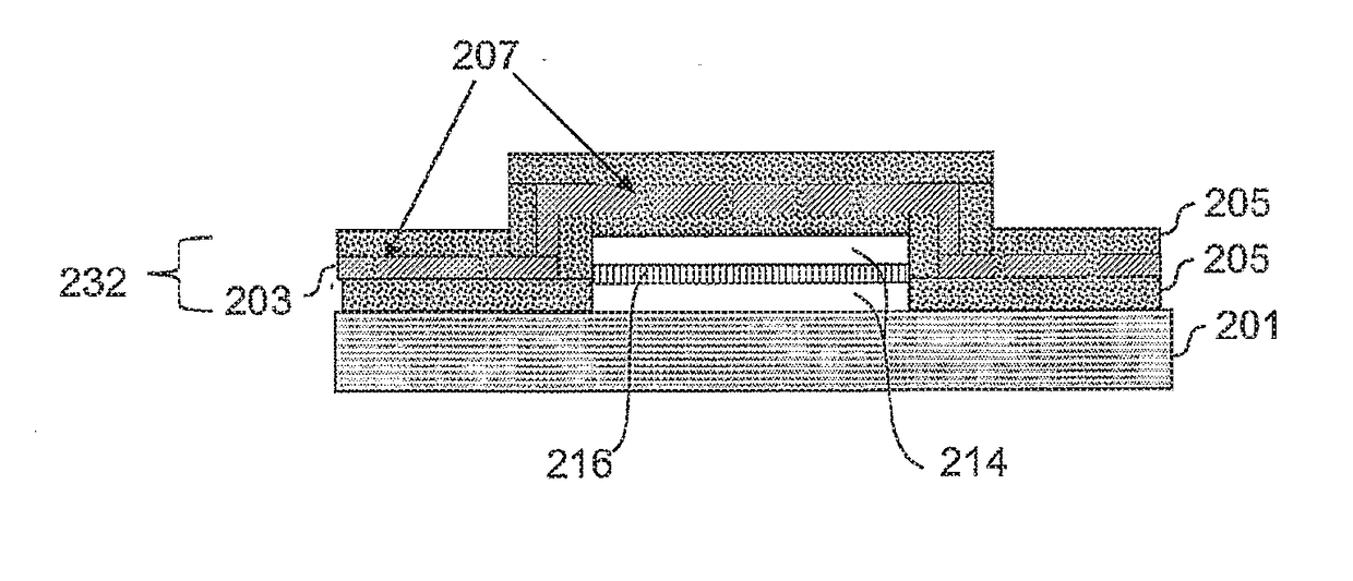
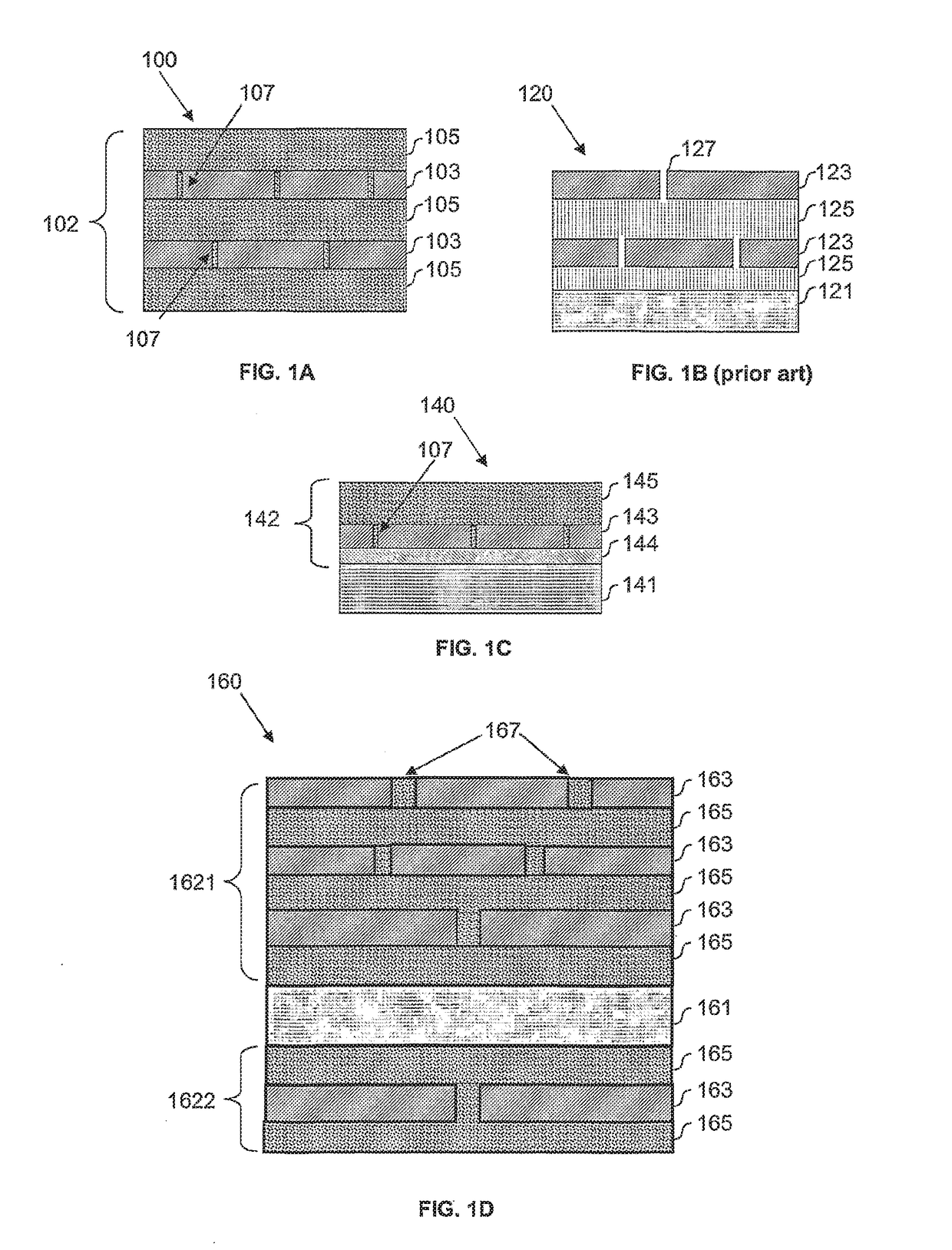
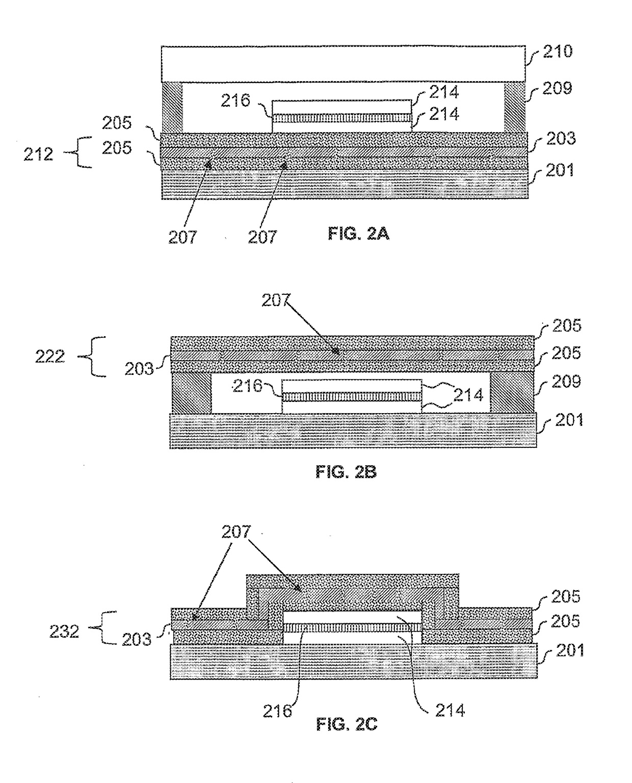
A barrier stack for encapsulating a moisture and / or oxygen sensitive electronic device is provided. The barrier stack comprises a multilayer film having at least one barrier layer having low moisture and / or oxygen permeability, and at least one sealing layer arranged to be in contact with a surface of the barrier layer, wherein the sealing material comprises reactive nanoparticles capable of interacting with moisture and / or oxygen, thereby retarding the permeation of moisture and / or oxygen through defects present in the barrier layer.

Description

CROSS-REFERENCE TO RELATED APPLICATIONS[0001]This patent application is a continuation of U.S. patent application Ser. No. 12 / 513,569, filed May 5, 2009, entitled NANOPARTICULATE ENCAPSULATION BARRIER STACK, which is a U.S. National Phase Application under 35 U.S.C. 371 of International Application No. PCT / SG2006 / 000334, filed Nov. 6, 2006, entitled NANOPARTICULATE ENCAPSULATION BARRIER STACK.FIELD[0002]The present invention relates generally to the field of encapsulation barrier stacks, and more particularly to encapsulation barrier stacks comprising reactive nanoparticles.BACKGROUND OF THE INVENTION[0003]Organic Light Emitting Displays (OLEDs) are widely seen as the next generation display technology that will come to replace existing display technology. Amongst the various challenges to be dealt with in the development of OLEDS, effective encapsulation remains one of the most significant.[0004]One commonly known problem with OLED structures and other oxygen and / or moisture sensit...

Claims


Application Information

Patent Timeline
Patent Type & Authority Applications(United States)
IPC IPC(8): H01L51/52
CPCH01L51/5256B82Y15/00H01L2251/5369H01L51/5259Y10T428/25H10K50/846H10K50/8445H10K2102/331B32B27/02C09K11/00H05B33/04B82Y30/00B82Y20/00B82Y25/00
Inventor RAMADAS, SENTHIL KUMARCHUA, SOO JIN
Owner AGENCY FOR SCI TECH & RES
Learn More