
Releasable Delivery System

a delivery system and a technology of a stent are applied in the field of stents, which can solve the problems of inability to adjust the stent, the stent is not easily removed, so as to achieve the effect of increasing the width of the channel

Active Publication Date: 2017-03-23
MICROVENTION INC
View PDF7 Cites 184 Cited by
  • Summary
  • Abstract
  • Description
  • Claims
  • Application Information

AI Technical Summary

Benefits of technology

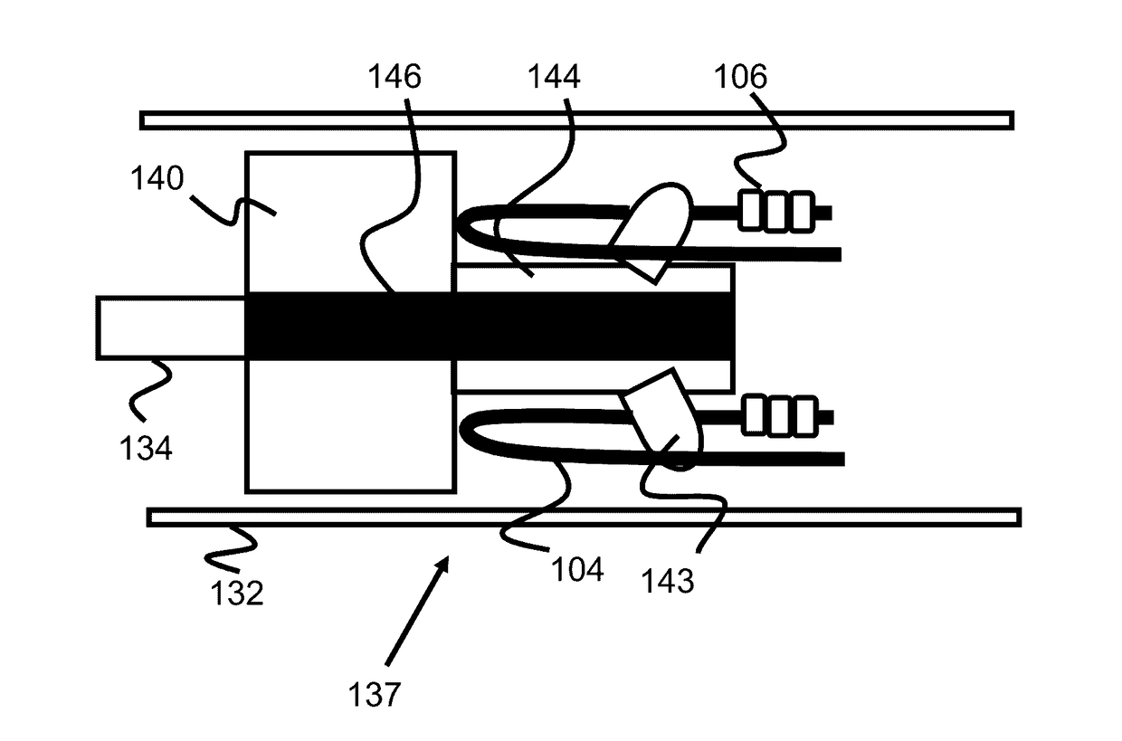
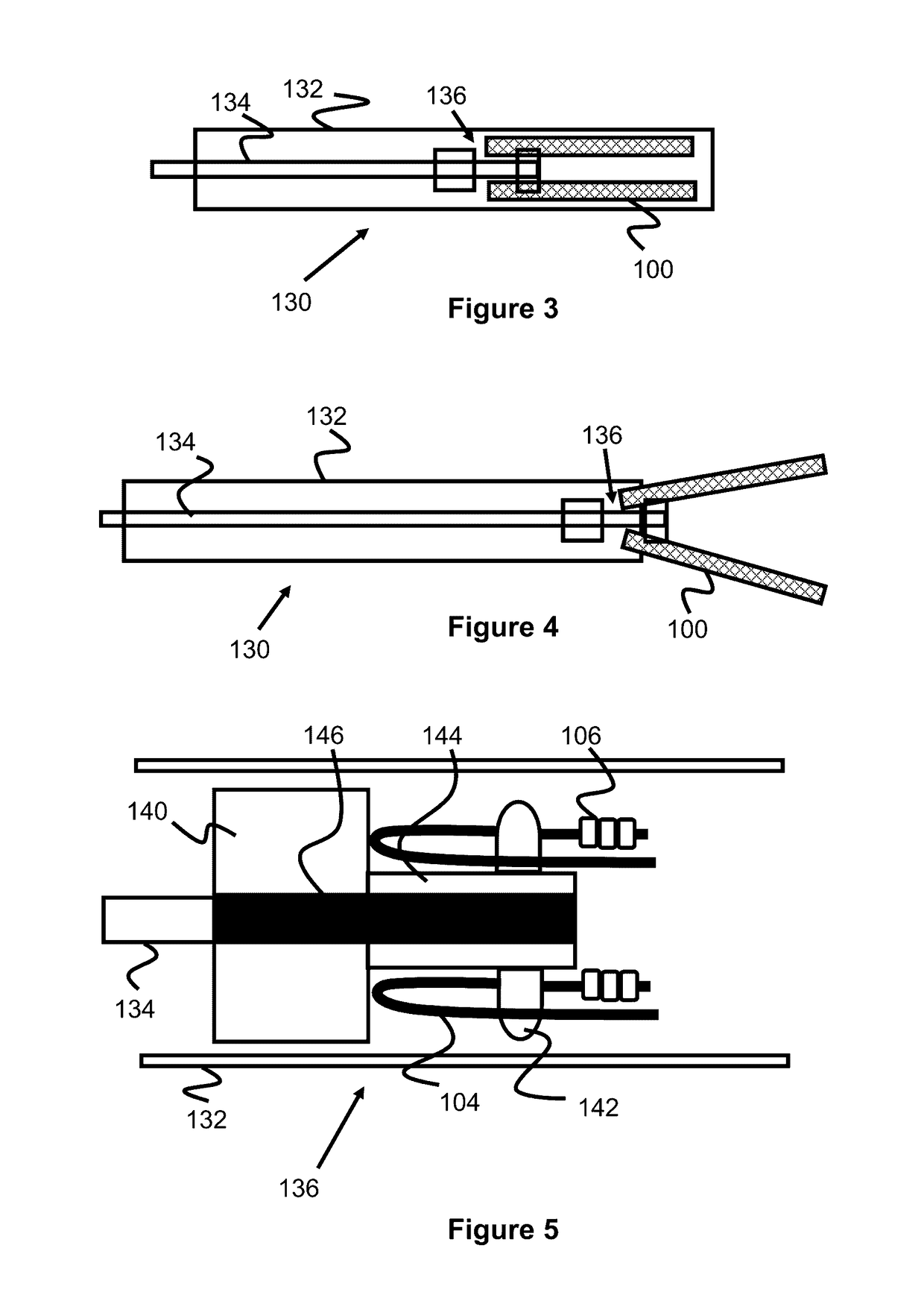
The invention is a delivery system that has a pusher with a tubular body that has multiple channels. These channels are located around the stent's loops and allow the stent to be removed back into its delivery sheath. The end of the tubular body is designed to expand when it is advanced out of the delivery sheath. This expansion causes the channels to widen and release the stent's loops. The technical effect is the ability to securely hold and release the stent during delivery without causing damage or difficulty.

Problems solved by technology

However, stents are not always deployed in the precise position that physician may intend, and therefore it can be desirable to retract the stent back into the sheath prior to its final deployment.

Method used


Image

  • Releasable Delivery System
  • Releasable Delivery System
  • Releasable Delivery System

Examples


Embodiment Construction

[0025]Specific embodiments of the invention will now be described with reference to the accompanying drawings. This invention may, however, be embodied in many different forms and should not be construed as limited to the embodiments set forth herein; rather, these embodiments are provided so that this disclosure will be thorough and complete, and will fully convey the scope of the invention to those skilled in the art. The terminology used in the detailed description of the embodiments illustrated in the accompanying drawings is not intended to be limiting of the invention. In the drawings, like numbers refer to like elements.

[0026]Stents are often delivered with delivery devices comprising a sheath or catheter and an elongated pusher within that catheter. Once the distal end of the sheath is located at a desired location, the sheath is either retracted or the pusher is used to push the stent out of the sheath. However, stents are not always deployed in the precise position that ph...


PUM


Abstract

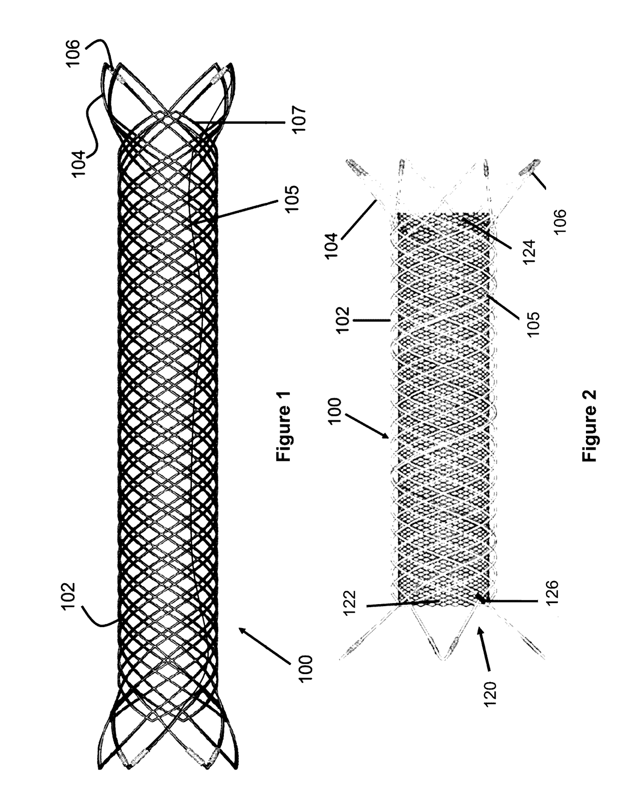
Implant engagement mechanisms are disclosed for maintaining engagement with a stent until it has been fully deployed and expanded from a catheter or sheath. The apparatus, method and system involving these engagement mechanisms allow a physician to withdraw or retract a sheath prior to full deployment, thereby allowing for redeployment of the stent at a more desirable position.

Description

RELATED APPLICATIONS[0001]This application claims priority to U.S. Provisional Application Ser. No. 62 / 220,910 filed Sep. 18, 2015 entitled Releasable Implant Delivery System, which is hereby incorporated herein by reference in its entirety.BACKGROUND OF THE INVENTION[0002]Medical implants such as stents or stent grafts can also be used to open blood vessels to mitigate the effects of plaque buildup, as a scaffold to keep embolic material within an aneurysm, as a flow diverter to limit blood flow to certain regions, or for other reasons.[0003]Stents or other implants are often delivered with delivery devices comprising a sheath or catheter and an elongated pusher within that catheter. Once the distal end of the sheath is located at a desired location, the sheath is either retracted or the pusher is used to push the stent out of the sheath. However, stents are not always deployed in the precise position that physician may intend, and therefore it can be desirable to retract the stent...

Claims


Application Information

Patent Timeline
Patent Type & Authority Applications(United States)
IPC IPC(8): A61F2/966A61F2/82
CPCA61F2/966A61F2230/0069A61F2/82A61F2/88A61F2002/9665A61F2250/0098
Inventor PUNG, PONAKATIEU, TAI D.SOLTANIAN, ROSSNGUYEN, HELENNGUYEN, OANHNGO, BRITNEY
Owner MICROVENTION INC
Learn More