
Method of producing synthetic resin stamp

a synthetic resin and stamp technology, applied in the field of synthetic resin stamp production, can solve the problems of burning residue of rubber raw materials that tend to stick to the seal face, strong odor tends to generate, etc., and achieve the effect of preventing strong odor, easy removal of burnt residue, and improving cleaning step

Inactive Publication Date: 2017-03-09
TAIYOTOMAH
View PDF2 Cites 0 Cited by
  • Summary
  • Abstract
  • Description
  • Claims
  • Application Information

AI Technical Summary

Benefits of technology

The present invention molds material without using a vulcanization agent or promoting agent, which prevents odor and environmental hazards. After laser engraving, the seal surface is easy to clean with water or brushing.

Problems solved by technology

In the conventional synthetic resin stamp using the rubber raw material, when a seal face is produced through a laser engraving process, strong odor tends to generate.
Further, a burnt residue of the rubber raw material tends to stick to the seal face after the seal face is produced through the laser engraving process.

Method used


Image

  • Method of producing synthetic resin stamp
  • Method of producing synthetic resin stamp
  • Method of producing synthetic resin stamp

Examples


example no.1

EXAMPLE NO. 1

[0046]An example No. 1 of the embodiment of the present invention will be explained next. In the example No. 1, 70 parts of the thermoplastic elastomer, 30 parts of an ultra low-density polyethylene, 70 parts of the filling material (talc), 4 parts of the cross-linking agent, and 4 parts of the foaming agent are uniformly mixed to obtain a uniform mixture. Then, the uniform mixture is processed and kneaded with a twin screw extruder to obtain the molding material (the example No. 1).

example no.2

EXAMPLE NO. 2

[0047]An example No. 2 of the embodiment of the present invention will be explained next. In the example No. 2, 30 parts of the thermoplastic elastomer, 70 parts of an ultra low-density polyethylene, 70 parts of the filling material (talc), 4 parts of the cross-linking agent, and 4 parts of the foaming agent are uniformly mixed to obtain a uniform mixture. Then, similar to the example No. 1, the uniform mixture is processed and kneaded with the twin screw extruder to obtain the molding material (the example No. 2).

example no.3

EXAMPLE NO. 3

[0048]An example No. 3 of the embodiment of the present invention will be explained next. In the example No. 3, 50 parts of ethylene vinyl acetate co-polymer (a vinyl acetate content is 20%), 70 parts of an ultra low-density polyethylene, 70 parts of the filling material (talc), 4 parts of the cross-linking agent, and 4 parts of the foaming agent are uniformly mixed to obtain a uniform mixture. Then, similar to the example No. 1, the uniform mixture is processed and kneaded with the twin screw extruder to obtain the molding material (the example No. 3).

[0049]An experiment was conducted to evaluate the example No. 1 to the example No. 3 obtained through the process described above.

[0050]In the experiment, 340 g of the molding materials of the examples No. 1 to No. 3 were placed in a metal frame having a thickness of 7.5 mm and an inner volume of 274 cm3. Then, the metal frame was heated at 190° C. for five minutes, so that the molding materials of the examples No. 1 to N...


PUM

PropertyMeasurementUnit
decomposition temperatureaaaaaaaaaa
cross-linking temperatureaaaaaaaaaa

Abstract

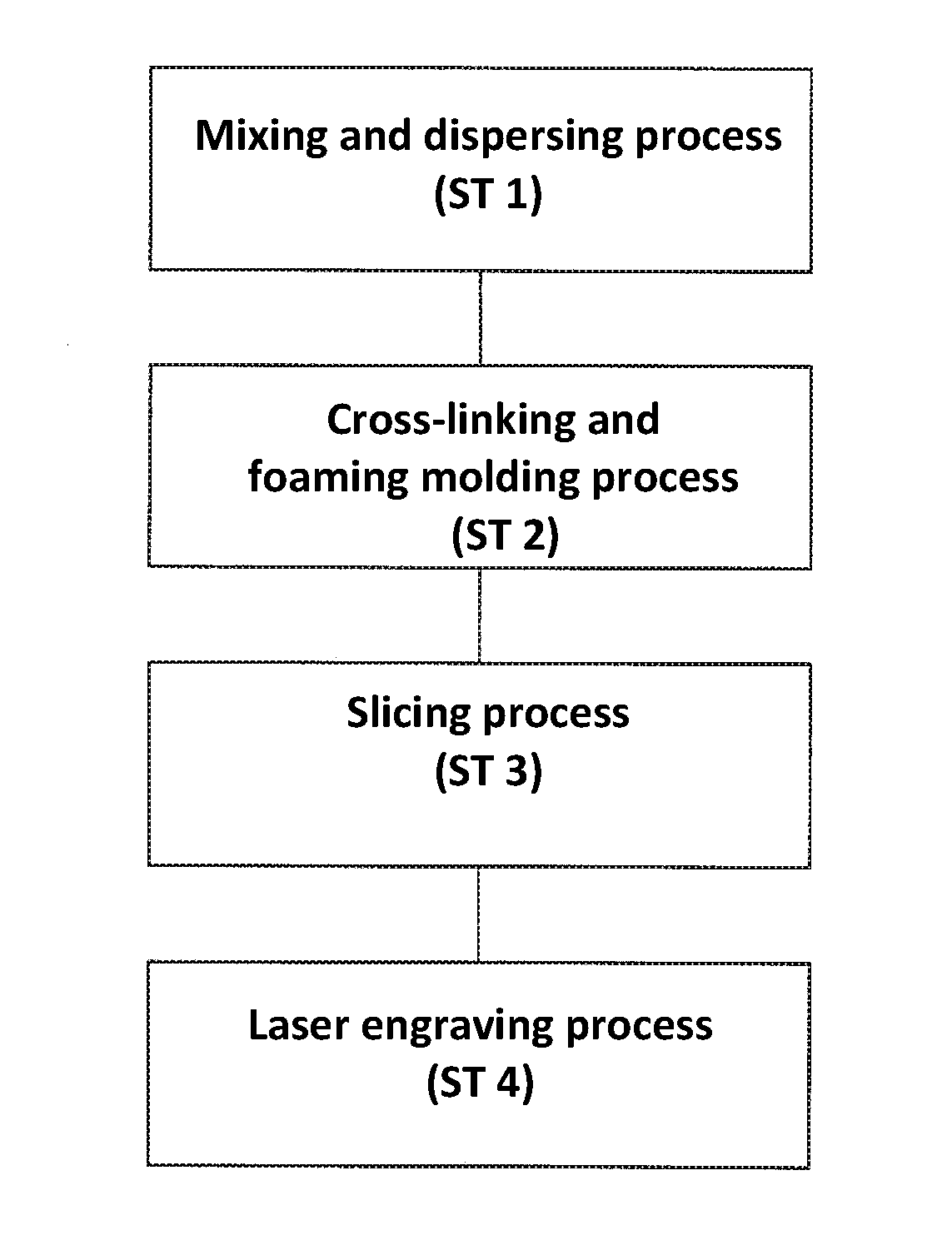
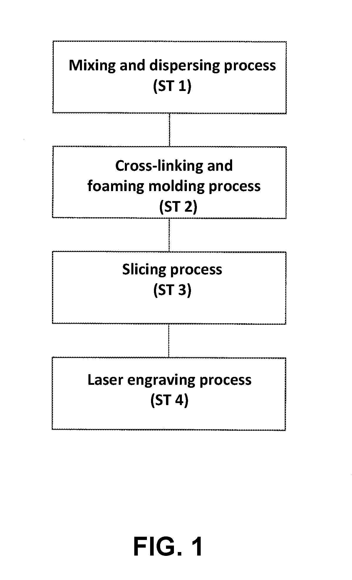
A method of producing a synthetic resin stamp includes the steps of mixing 35 to 45 weight % of a polyethylene resin, 11 to 22 weight % of a thermoplastic elastomer, 35 to 45 weight % of a filling material, 2 to 7 weight % of a cross-linking agent, and 2 to 7 weight % of a foaming agent to obtain a molding material; placing the molding material in a molding die; performing a direct pressure molding at 160° C. to 190° C. for 3 to 10 minutes for performing a cross-linking reaction and a foaming reaction to obtain a foamed molded member formed of foam cells; slicing the foamed molded member to obtain a sliced member; and performing a laser engraving process on a surface of the sliced member to obtain the synthetic resin stamp.

Description

BACKGROUND OF THE INVENTION AND RELATED ART STATEMENT[0001]The present invention relates to a method of producing a synthetic resin stamp having a seal face formed through a laser engraving process.[0002]Patent Reference has disclosed a conventional synthetic resin stamp. According to Patent Reference, the conventional synthetic resin stamp is formed of a base rubber containing calcium carbonate as a rubber raw material thereof.[0003]Patent Reference: Japanese Patent Publication No. 11-42842[0004]In the conventional synthetic resin stamp using the rubber raw material, when a seal face is produced through a laser engraving process, strong odor tends to generate. Further, a burnt residue of the rubber raw material tends to stick to the seal face after the seal face is produced through the laser engraving process. Accordingly, it is necessary to perform an additional step to remove the burnt residue of the rubber raw material.[0005]In view of the problems described above, an object of ...

Claims


Application Information

Patent Timeline
Patent Type & Authority Applications(United States)
IPC IPC(8): B29C33/38
CPCB29C33/3842B29L2031/757B29K2023/06B29L2031/767B29K2021/003B29K2105/04B29K2105/16B29K2105/24B29C44/02B29C44/3415B29C44/5627B41D7/00
Inventor MATSUSHITA, IKUZONAGATA, YOSHIAKI
Owner TAIYOTOMAH
Learn More