Fuel cell

Active Publication Date: 2017-03-02
NGK INSULATORS LTD
View PDF3 Cites 4 Cited by
  • Summary
  • Abstract
  • Description
  • Claims
  • Application Information

AI Technical Summary

Benefits of technology

The present invention is about a fuel cell that can prevent damage to its solid electrolyte layer.

Problems solved by technology

However, since each member that configures the fuel cell has a different coefficient of thermal expansion, damage may result to the solid electrolyte layer during firing or operation of the fuel cell as a result of stress concentration.

Method used


Image

  • Fuel cell
  • Fuel cell
  • Fuel cell

Examples


examples

Preparation of Sample No. 1

[0081]A fuel cell stack according to Sample No. 1 is prepared as described below.

[0082]Firstly, a mixed powder is prepared by drying a slurry of a mixture of IPA and a compounding powder of a pore-forming agent (PMMA), 8YSZ powder and NiO powder in a nitrogen atmosphere.

[0083]Next, uniaxial pressing (compaction pressure 50 MPa) is applied to the mixed powder to form a plate, and a green body for the anode is prepared by further consolidation of the plate by use of a CIP (compaction pressure: 100 MPa).

[0084]Next, a slurry for the solid electrolyte layer is prepared by mixing terpineol and a binder with a cubic crystal zirconia powder. In Sample No. 1, tetragonal crystal zirconia powder is not added to the slurry for the solid electrolyte layer.

[0085]Next, a green body for the solid electrolyte layer is formed by coating the slurry for the solid electrolyte layer using a screen printing method or the like onto the green body for the anode.

[0086]Next, the gre...


PUM

PropertyMeasurementUnit
Ratioaaaaaaaaaa

Abstract

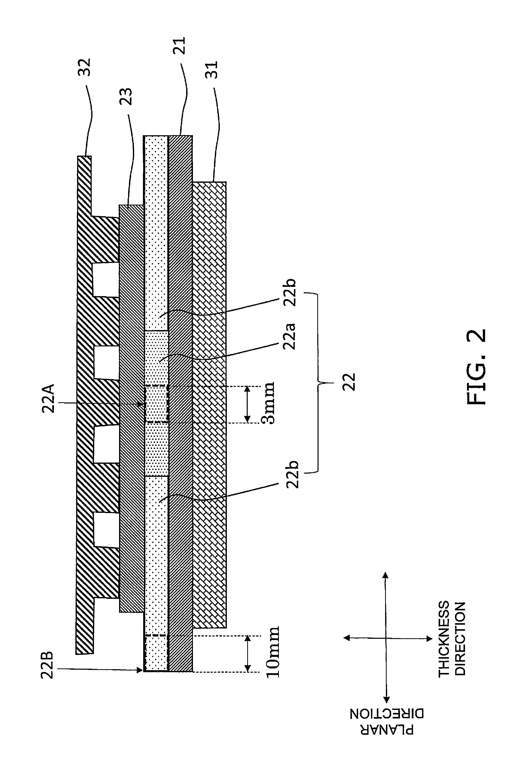
A fuel cell comprises an anode, a cathode, and a solid electrolyte layer disposed between the anode and the cathode. The solid electrolyte layer contains a zirconia-based material as a main component. A first intensity ratio of tetragonal crystal zirconia to cubic crystal zirconia in a Raman spectrum in a central portion of the solid electrolyte layer is greater than a second intensity ratio of tetragonal crystal zirconia to cubic crystal zirconia in a Raman spectrum of an outer edge.

Description

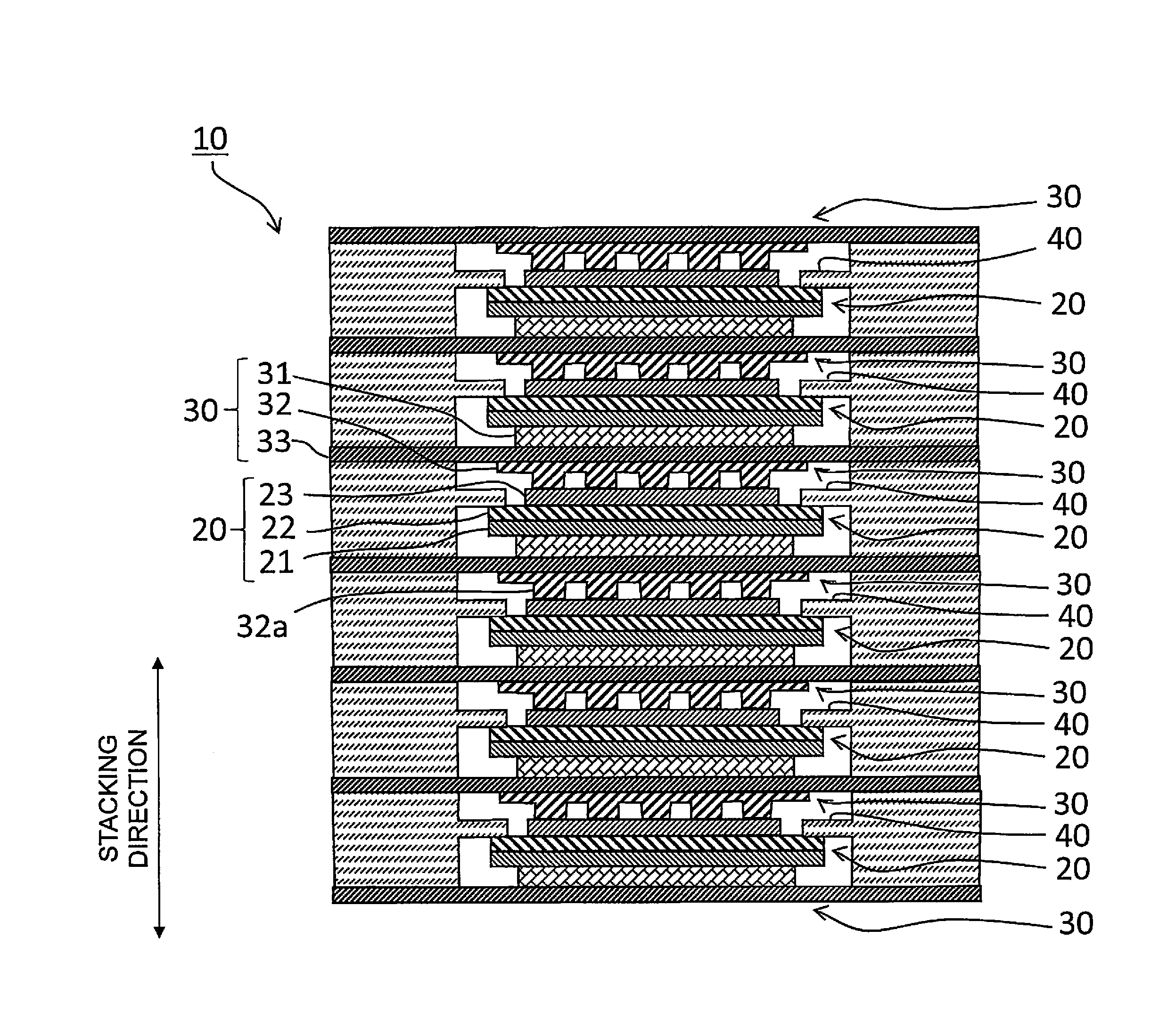
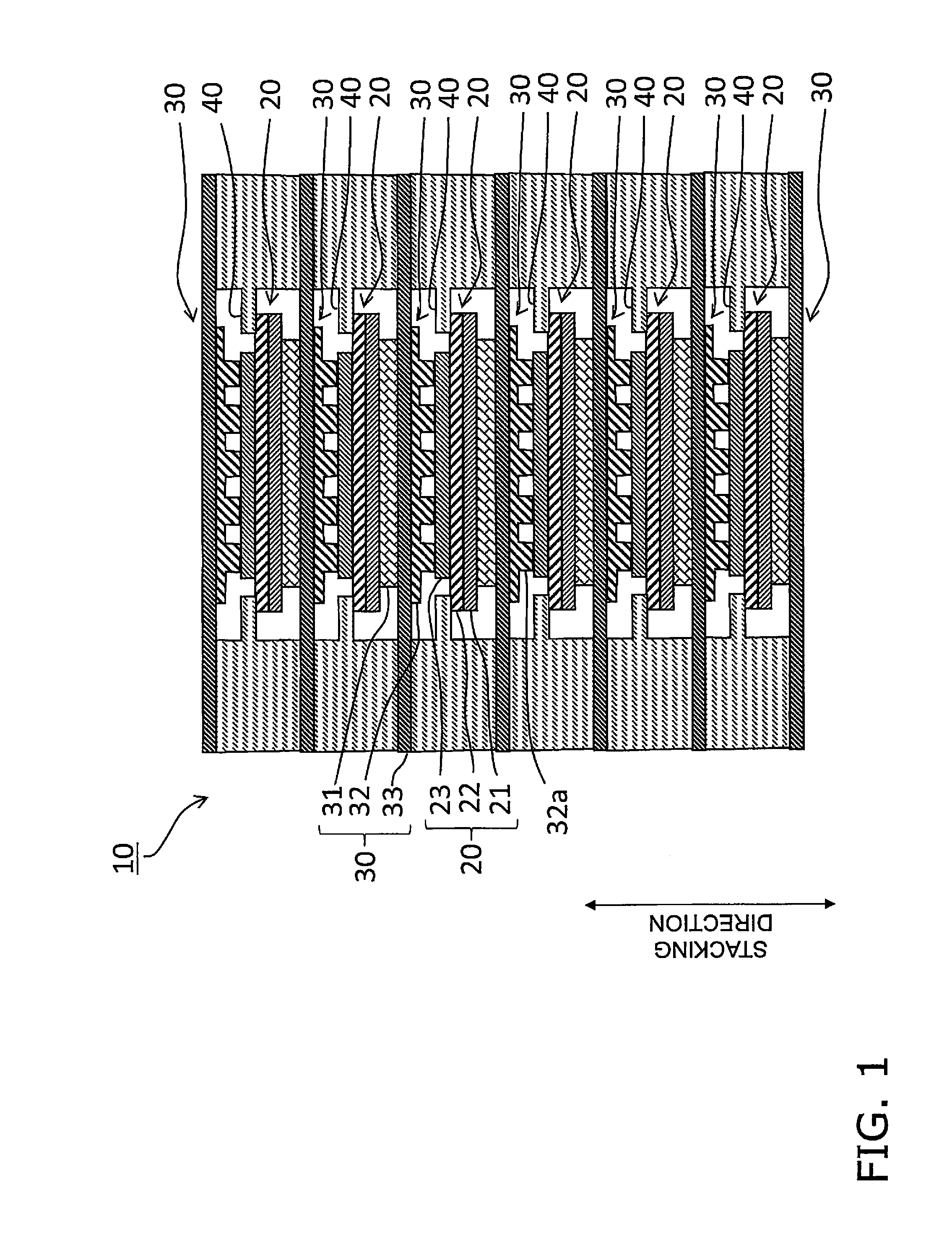
TECHNICAL FIELD[0001]The present invention relates to a fuel cell.BACKGROUND ART[0002]A fuel cell stack is known to be typically configured by alternate stacking of a tabular fuel cell and a metal current collecting member (For example, reference is made to Japanese Patent Application Laid-Open No. 2008-135272).[0003]The fuel cell includes an anode, a cathode and a solid electrolyte layer between the anode and the cathode.SUMMARY OF INVENTION[0004]However, since each member that configures the fuel cell has a different coefficient of thermal expansion, damage may result to the solid electrolyte layer during firing or operation of the fuel cell as a result of stress concentration.[0005]The present invention is proposed in light of the above circumstances, and has the object of providing a fuel cell that can suppress damage to the solid electrolyte layer.[0006]The fuel cell according to the present invention comprises an anode, a cathode, and a solid electrolyte layer disposed between...

Claims


Application Information

Patent Timeline
IPC IPC(8): H01M8/1253H01M8/2425H01M4/90
CPCH01M8/1253H01M4/9025H01M2008/1293H01M8/2425H01M4/9033C04B35/486C04B2235/3225C04B2235/3246C04B2235/75C04B2235/762C04B2235/765H01M4/8889H01M8/0223H01M8/0247H01M2300/0077H01M2300/0088H01M8/2432Y02E60/50Y02P70/50
Inventor OHMORI, MAKOTOFUJISAKI, SHINJI
Owner NGK INSULATORS LTD
Why Eureka
Try Eureka