
Expander

a technology of expanders and expanders, applied in the field of expanders, can solve the problems of bearing damage, bearing durability degradation, bearing damage, etc., and achieve the effects of suppressing damage and durability of the bearing of the expander, preventing oil shortage, and suppressing damage and durability of the first bearing

Inactive Publication Date: 2014-12-04
KOBE STEEL LTD
View PDF7 Cites 4 Cited by
  • Summary
  • Abstract
  • Description
  • Claims
  • Application Information

AI Technical Summary

Benefits of technology

The present invention aims to solve the problems of bearing damage and degradation in durability during the activation of an expander. It simplifies the configuration of the expander, reduces manufacturing costs, and prevents oil shortage in the bearing. It achieves this by discharging lubricant through a separate passage, preventing the lubricant from accumulating in the bearing chamber and causing power loss. It also prevents oil shortage in the pair of first bearings and ensures the durability of the bearings.

Problems solved by technology

In the expander of the related art, since the lubricant flows and falls from the bearing to the oil reservoir, there is a case in which oil shortage may occur in the bearing during the activation of the expander.
Accordingly, there is a concern that the bearing may be damaged or the durability of the bearing may be degraded.
Further, since the oil reservoir is formed between the housing and the rotary scroll and the cooling medium pump is provided to discharge the cooling medium and the lubricant having been used for the lubrication, the configuration of the expander becomes complicated, and the manufacturing cost increases.

Method used


Image

  • Expander
  • Expander
  • Expander

Examples


Embodiment Construction

[0029]Hereinafter, an embodiment of the present invention will be described with reference to the drawings.

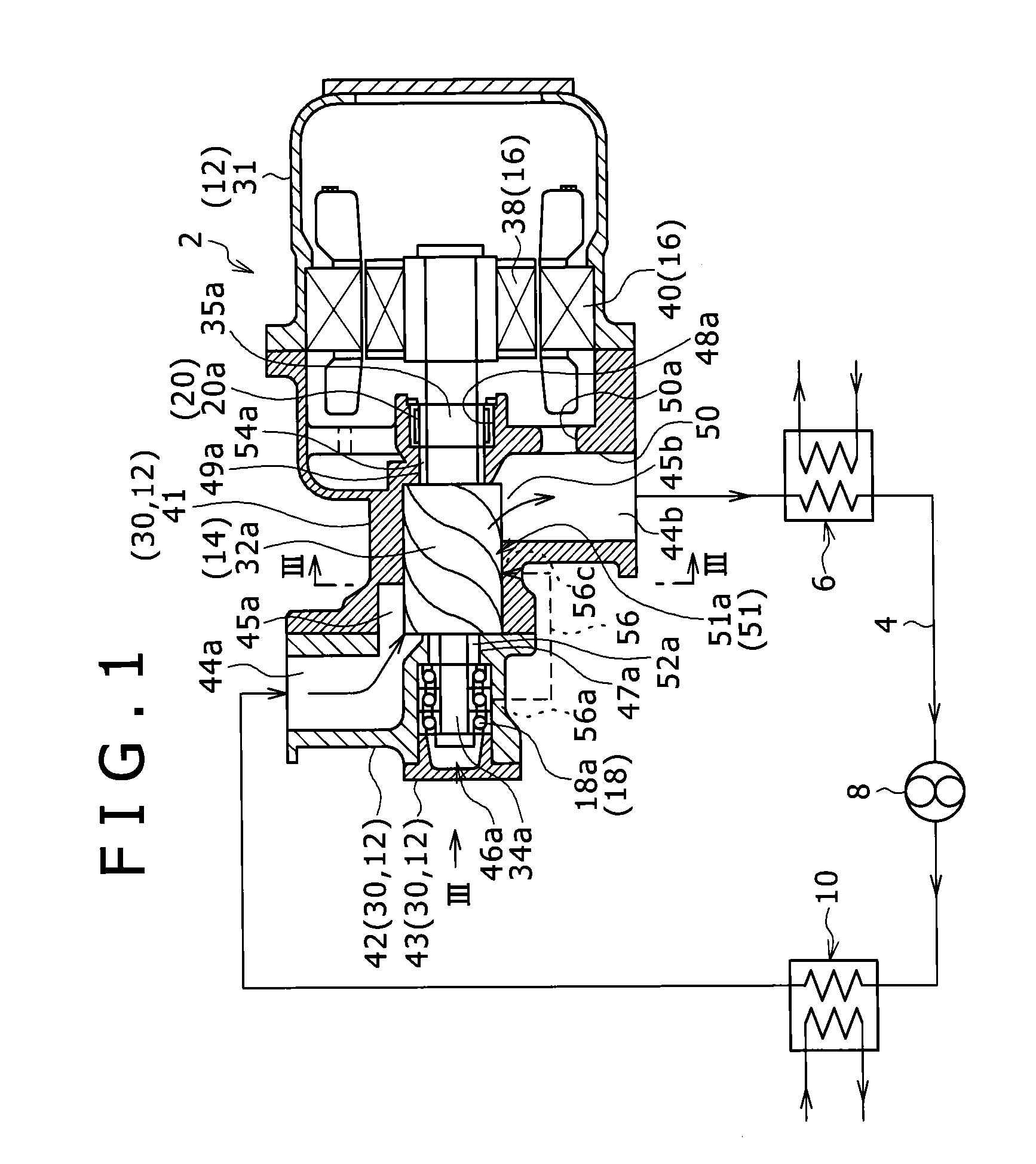
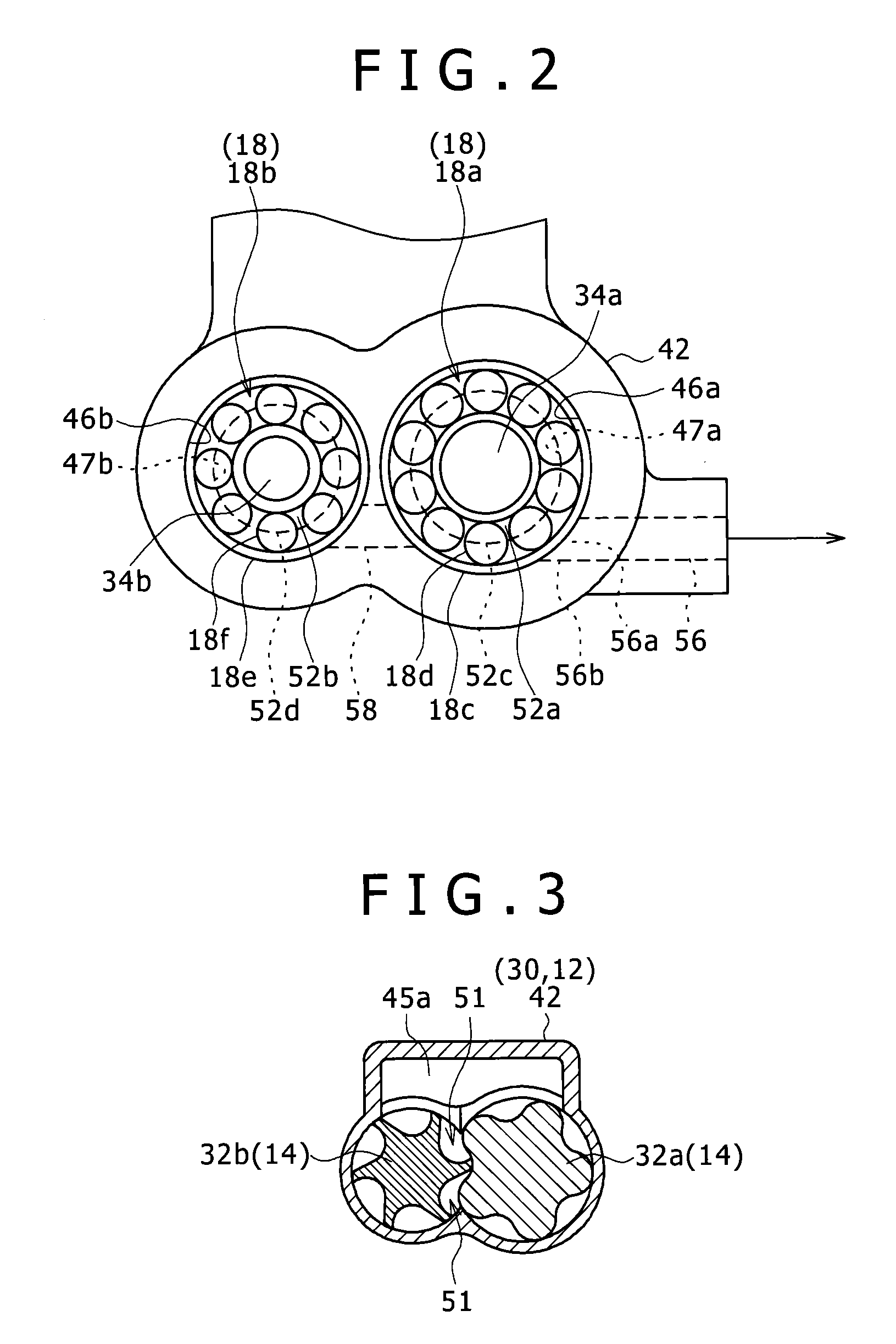
[0030]FIG. 1 illustrates a power generation system that uses an expander of this embodiment. The power generation system is a power generation system that uses a Rankine cycle and adopts a binary generation system in which power is recycled from low-temperature exhaust heat by the use of a working medium with a low boiling point. As the working medium, for example, a cooling medium such as R245fa (1, 1, 1, 3, 3-Pentafluoropropane) is used. As shown in FIG. 1, the power generation system includes a power generation apparatus 2, a circulation flow passage 4, a condenser 6, a circulation pump 8, and an evaporator 10.

[0031]Although the detailed structure of the power generation apparatus 2 will be described below, the power generation apparatus 2 includes a screw-type expander 14 and a generator 16. In the power generation apparatus 2, expander rotors 32a and 32b to be described la...


PUM


Abstract

In order to suppress the damage and the degradation in durability of a bearing of an expander, simplify the configuration of the expander, and reduce the manufacturing cost thereof, an expander of the present invention includes an expander rotor that is rotationally driven by an expanding force transmitted from vapor of a working medium introduced into an expansion chamber and a first bearing that supports a first rotation shaft of the expander rotor to a vapor inlet, a casing includes therein first bearing chambers that have a pressure lower than that of the vapor inlet and accommodate the first bearing, and a passage that leads lubricant to a low-pressure portion having a pressure lower than that of the first bearing chamber is connected to a position above the lowermost portion of the first bearing in the first bearing chamber.

Description

BACKGROUND OF THE INVENTION[0001]1. Field of the Invention[0002]The present invention relates to an expander.[0003]2. Description of the Related Art[0004]A power generation apparatus disclosed in Japanese Patent No. 4684882 includes an expander, a generator, and a cooling medium pump which are disposed in order from the downside toward the upside and are integrated with one another.[0005]The expander includes a rotary scroll that is rotated by the expansion of a vapor cooling medium flowing into a working chamber. The generator includes a motor shaft that is connected to the rotary scroll through a shaft and a rotor that is attached to the motor shaft. In the generator, power is generated by the rotation of the motor shaft and the rotor using the rotational movement of the rotary scroll transmitted through the shaft. A bearing that supports the motor shaft is provided inside a housing of the generator.[0006]A vapor cooling medium including lubricant is introduced into the working ch...

Claims


Application Information

Patent Timeline
IPC IPC(8): F01C21/02F01C19/12F01C21/04F01C1/02
CPCF01C21/02F01C21/04F01C19/125F01C1/02F01C1/16F04C2240/52
Inventor TSUBOI, NOBORU
Owner KOBE STEEL LTD
Learn More