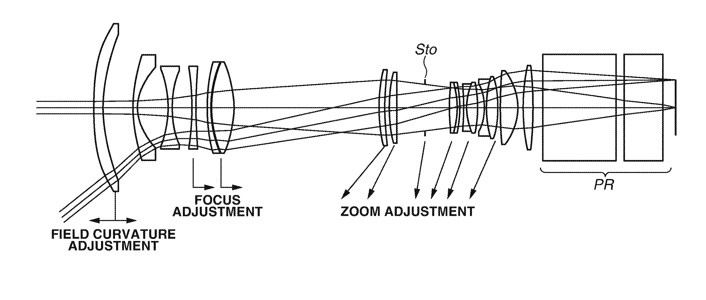
Projection optical system and projection type display apparatus using the same
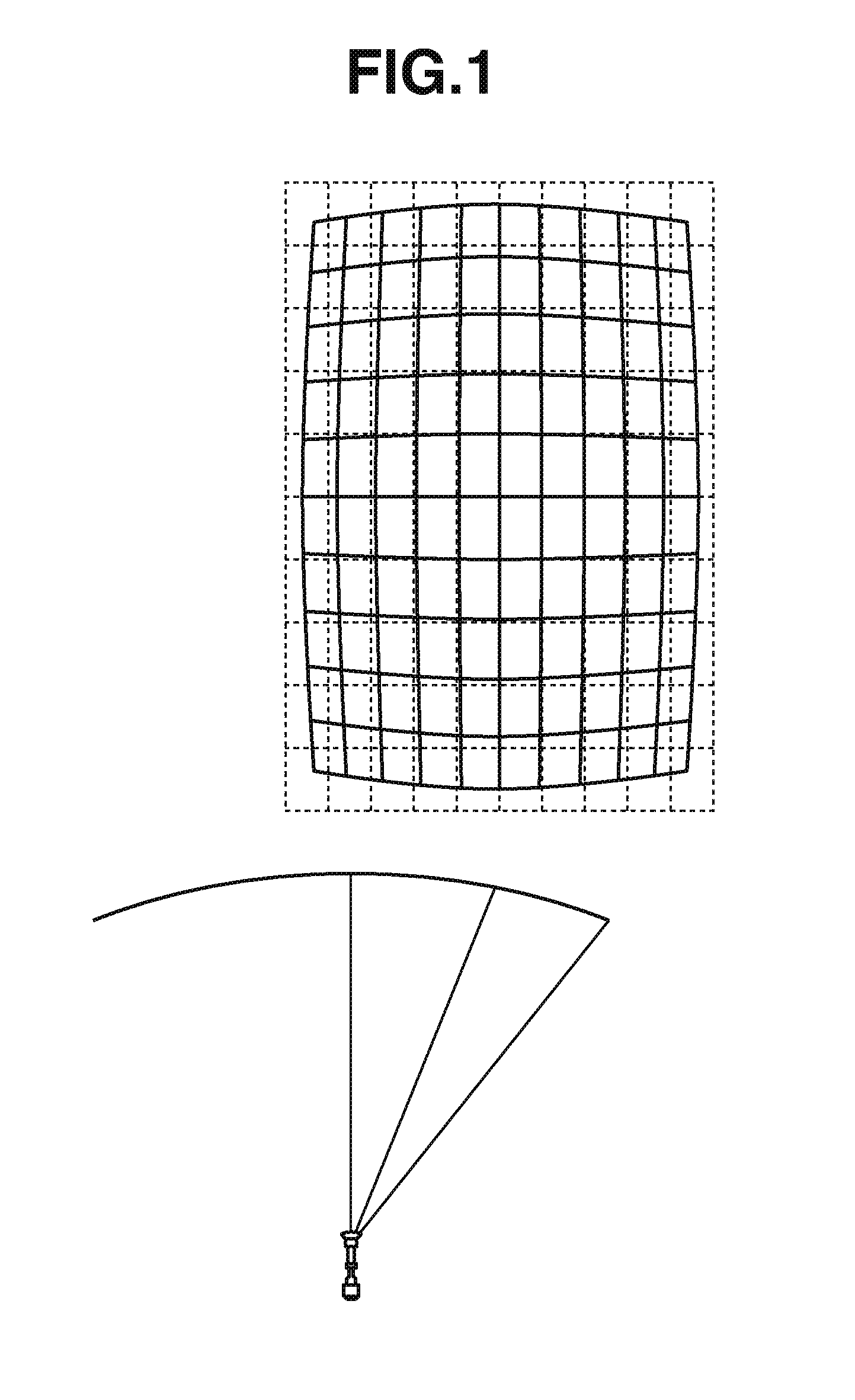
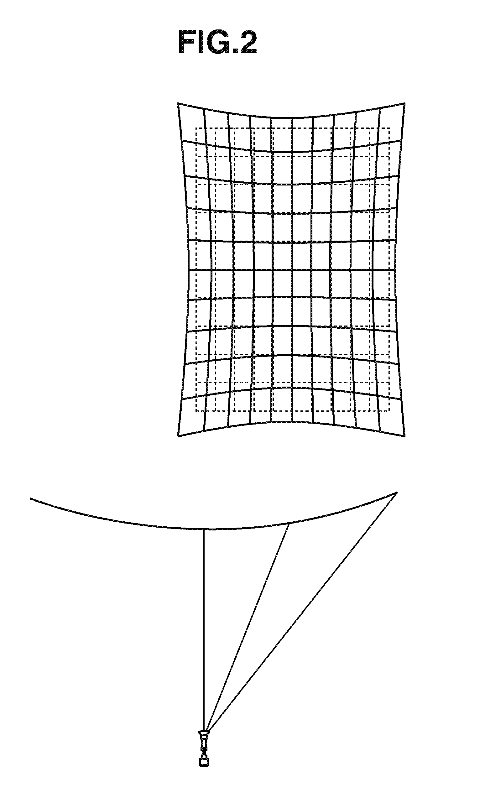
a projection optical system and projection type technology, applied in the direction of instruments, mountings, projectors, etc., can solve the problems of changing the size of the projected image, other positions are out of focus,
- Summary
- Abstract
- Description
- Claims
- Application Information
AI Technical Summary
Benefits of technology
Problems solved by technology
Method used
Image

Examples
numerical examples
[0096]Numerical examples of the respective exemplary embodiments will be described below. A surface number is a number sequentially attached to a surface of each lens from the enlargement side, φea represents an effective diameter of each lens, R represents a curvature radius of each lens surface, d represents a surface interval, and Nd and νd represent refractive index and Abbe number of a glass material with respect to the d-line (587.56 nm). The lens surface marked with s at the right of the surface number represents an aperture stop. The lens surface marked with * (asterisk) at the right of the surface number is aspherical. When y is a coordinate in the diameter direction with the surface vertex of the lens surface being used as a reference, and x is the above-described sagittal amounts SAG1 and SAG2, the aspherical shape is represented by the following equation as the coordinate in the optical axis direction when the surface vertex of the lens surface is defined as a reference....
numerical example 1
[0099]
f = 17.07−22.18 ω = 38.3−31.3 FNO = 2.6 Φ = 27.08SUR ΦeaOBJ 1534.00RdGLASSNdυd 1*76.00227.87944.35SBSL71.5163364.14269.8979.985015.00 3*49.3866.84972.60SLAL81.7130053.87440.2827.596515.70537.87−52.82862.00SFPL511.4970081.54636.4750.8683(VARIABLE)737.62−122.21702.00SLAM21.7440044.79838.55243.6367(VARIABLE)941.99100.58652.30EFDS1W1.9228620.881042.3758.382611.20SNBH521.6730038.151143.08−53.5108(VARIABLE)1237.0772.72713.30SBAL351.5891361.131336.50140.7457(VARIABLE)1431.5876.03493.60FD60W1.8051825.461531.031029.7681(VARIABLE) 16s22.93INF(VARIABLE)1722.54450.51173.70SBSL71.5163364.141822.20−40.28071.30TAFD251.9036631.311922.18−68.5657(VARIABLE)2021.34−352.92451.20TAFD251.9036631.312121.5028.68855.90SBSL71.5163364.142222.34−48.2408(VARIABLE)2322.98−26.03761.30TAFD251.9036631.312426.0977.52065.75SBSL71.5163364.142528.42−48.12301.162632.66267.17798.75SFPL511.4970081.542734.46−30.1637(VARIABLE)2839.4889.14065.00SNPH11.8080922.762939.36−223.90525.003050.00INF37.00SBSL71.5163364.143150....
numerical example 2
[0100]
f = 17.07−22.18 ω = 38.3−31.3 FNO = 2.6 Φ = 27.08SURΦeaOBJ 1534.00RdGLASSNdυd 1*76.36246.15964.50SBSL71.5163364.14 2*70.4883.600714.00 3*49.1359.95092.60SLAL81.7130053.87440.3127.824815.00538.06−52.64242.00SFPL511.4970081.54636.1747.3397(VARIABLE)736.94−107.46112.00SLAM21.7440044.79837.88204.0220(VARIABLE)941.2598.03782.30EFDS1W1.9228620.881041.5956.203511.20SNBH521.6730038.151142.31−51.8320(VARIABLE)1235.4273.46483.30SBAL351.5891361.131334.81128.6670(VARIABLE)1431.6371.71423.60FD60W1.8051825.461531.101187.4460(VARIABLE) 16s22.92INF(VARIABLE)1722.52435.21473.70SBSL71.5163364.141822.19−40.37541.30TAFD251.9036631.311922.22−66.7994(VARIABLE)2021.42−196.53751.20TAFD251.9036631.312121.3929.19185.90SBSL71.5163364.142221.98−44.7197(VARIABLE)2322.41−25.40531.30TAFD251.9036631.312425.3676.00615.75SBSL71.5163364.142527.70−44.98811.162631.95261.32898.75SFPL511.4970081.542733.84−29.8326(VARIABLE)2839.0886.37815.00SNPH11.8080922.762938.94−247.12645.003050.00INF37.00SBSL71.5163364.143150...
PUM
 Abstract
Description
Claims
Application Information
 - R&D
- Intellectual Property
- Life Sciences
- Materials
- Tech Scout
- Unparalleled Data Quality
- Higher Quality Content
- 60% Fewer Hallucinations
Browse by: Latest US Patents, China's latest patents, Technical Efficacy Thesaurus, Application Domain, Technology Topic, Popular Technical Reports.
© 2025 PatSnap. All rights reserved.Legal|Privacy policy|Modern Slavery Act Transparency Statement|Sitemap|About US| Contact US: help@patsnap.com