Eureka AIR delivers breakthrough ideas for toughest innovation challenges, trusted by R&D personnel around the world.

Filter assembly with curved inlet guide

Active Publication Date: 2017-02-23
WL GORE & ASSOC INC
View PDF13 Cites 10 Cited by
  • Summary
  • Abstract
  • Description
  • Claims
  • Application Information

AI Technical Summary

Benefits of technology

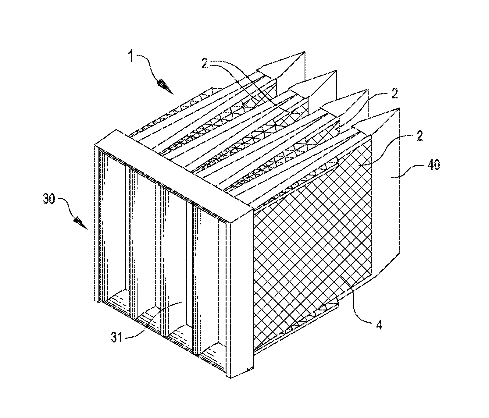
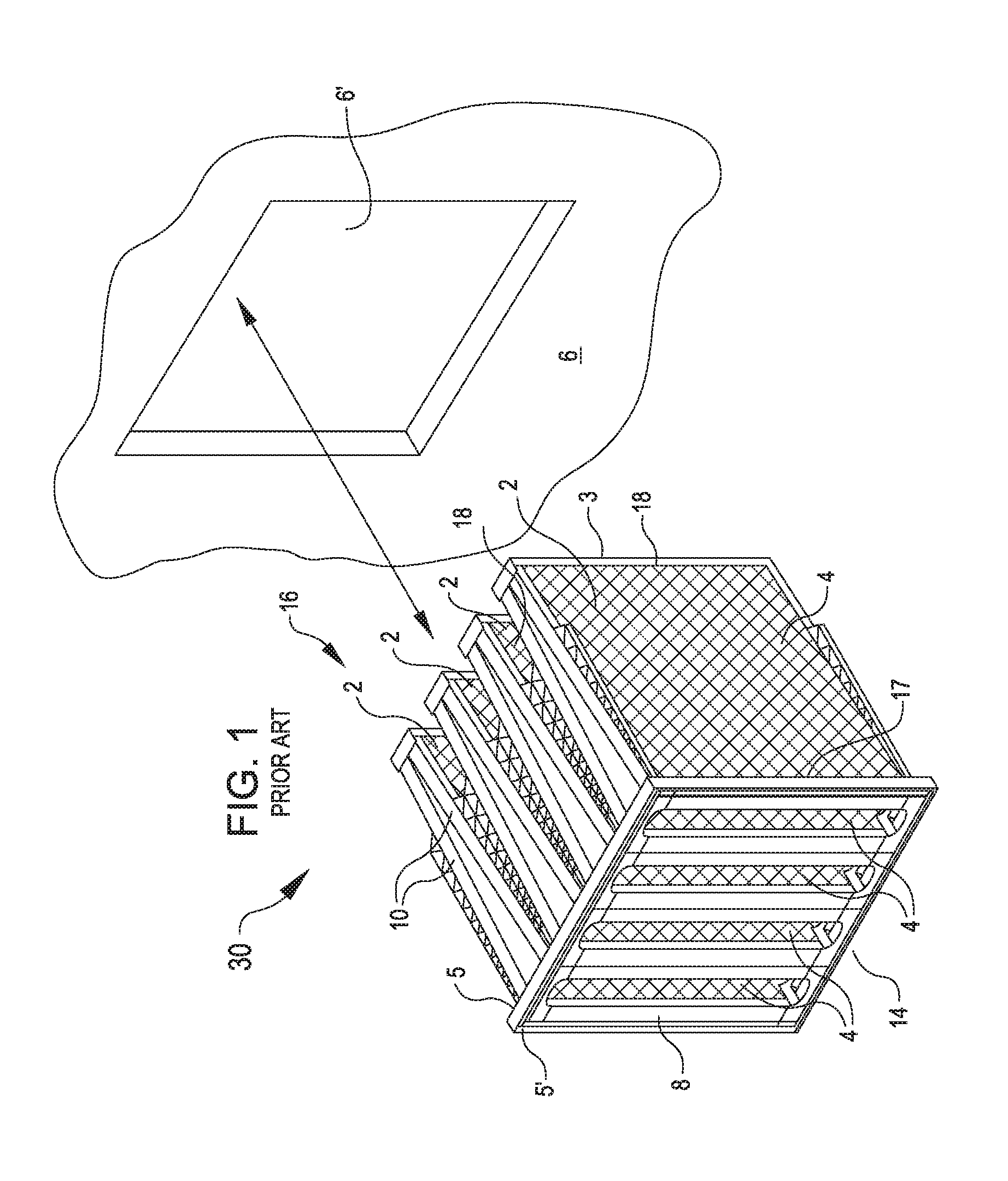
The invention relates to a filter assembly with an inlet guide and a cassette for holding a filter. The invention aims to reduce the pressure drop across the filter assembly. This is achieved by attaching an inlet guide to the upstream end of the filter cassette, which guides airflow through the filter cassette and reduces the pressure drop. An outlet guide may also be used to further reduce pressure drop downstream of the filter cassette. The invention reduces the pressure drop to below 500 Pa for a filter of Filter classE10 or greater, when the flow of air is 6,400 m3 / h or more.

Problems solved by technology

As may be appreciated, replacement of turbine componentry is not only expensive, but may also entail significant down time.
Many installations have limited space due to obstructions or installed equipment.
Such constraints limit the depth to which the cassette filter can extend into the clean side, and has therefore limited the size of cassette filters.
The size limitation limits the amount of media that can be installed in a filter.
This problem is particularly acute when retrofitting existing filter systems with high efficiency media.
The smaller footprint results in fewer filters in the housing and therefore higher airflow per filter and pressure drop.
Pressure drop has a negative impact on engine performance.
As a general rule, every 250 Pa increase of inlet pressure drop results in 0.4% penalty in engine power output and 1.67% increase in heat rate.
Such high flow rates dramatically increase the pressure drop across the filter.

Method used


Image

  • Filter assembly with curved inlet guide
  • Filter assembly with curved inlet guide
  • Filter assembly with curved inlet guide

Examples


example 1

[0054]The addition of circular shaped long sides 32 (as in the example shown in FIG. 3C, above), even without concomitant addition of circular short sides 33, 34, provided for reduced pressure drops across the entire filter assembly of about 7% for each tested flow rate.

example 2

[0055]The addition of lofted inlet guides of 25 mm, similar to short elliptical long and short sides 32, 33, 34 as shown in FIGS. 3A and 4A, provided even greater reduction in pressure drop across the filter. Both the long sides 32 and short sides 33, 34 were modified in this Example. At the lower volumetric flow rate of 6,400 m3 / h, the 25 mm lofted inlet guide provided for a reduction in pressure drop of about 11%; and at the higher volumetric flow rate 8,500 m3 / h, the 25 mm lofted inlet guide provided for a reduction in pressure drop of about 13%.

example 3

[0056]The addition of lofted inlet guides of 75 mm, similar to long elliptical long and short sides 32, 33, 34 as shown in FIGS. 3B and 4B, provided similarly promising reduction in pressure drops across the filter. At the lower volumetric flow rate, the 75 mm lofted inlet guide reduced the pressure drop by 12%; and at the higher volumetric flow rate, the 75 mm lofted inlet guide reduced the pressure drop by 14%.


PUM

PropertyMeasurementUnit
Pressureaaaaaaaaaa
Volumetric flow rateaaaaaaaaaa
Pressure dropaaaaaaaaaa

Abstract

A cassette filter assembly for removing particles from an air stream, in particular from a gas stream entering a gas turbine, has an upstream end and a downstream end and comprises a header frame to which a filter media is fitted and which has an inlet guide on said mounting face, the inlet guide having a plurality of openings, each opening being defined by a pair of lofted short sides and a pair of lofted long sides.

Description

CROSS-REFERENCES TO RELATED APPLICATIONS[0001]This patent application claims priority from U.S. Provisional Application Ser. No. 62 / 206,397, entitled “Filter Assembly With Curved Inlet Guide,” filed Aug. 18, 2015, the disclosure of which is incorporated herein by reference in its entirety.FIELD OF INVENTION[0002]The present invention relates to filter apparatus, and more particularly, to air intake filters utilized in industrial applications. The present disclosure may be used in filtration units used in a variety of applications, such as in emergency power generators, gas turbine, gas compressors, HVAC systems, gas mining operations, and the like.BACKGROUND[0003]Filters are employed in a wide range of applications, from usages to filter intake air in building ventilation systems to large scale industrial facilities and equipment. By way of example, air intake filters are utilized in connection with gas turbine combustion systems employed for power generation.[0004]In such applicati...

Claims


Application Information

Patent Timeline
IPC IPC(8): B01D46/00B01D46/52B01D46/12
CPCB01D46/0005B01D46/521B01D46/002B01D46/125B01D46/0041B01D46/0047B01D46/121
Inventor POON, WAI SINGKELMARTIN, THOMAS P.RAKESH, VINEET
Owner WL GORE & ASSOC INC
Why Eureka
Eureka Blog
Learn More