High polymer content hybrid drag reducers
- Summary
- Abstract
- Description
- Claims
- Application Information
AI Technical Summary
Benefits of technology
Problems solved by technology
Method used
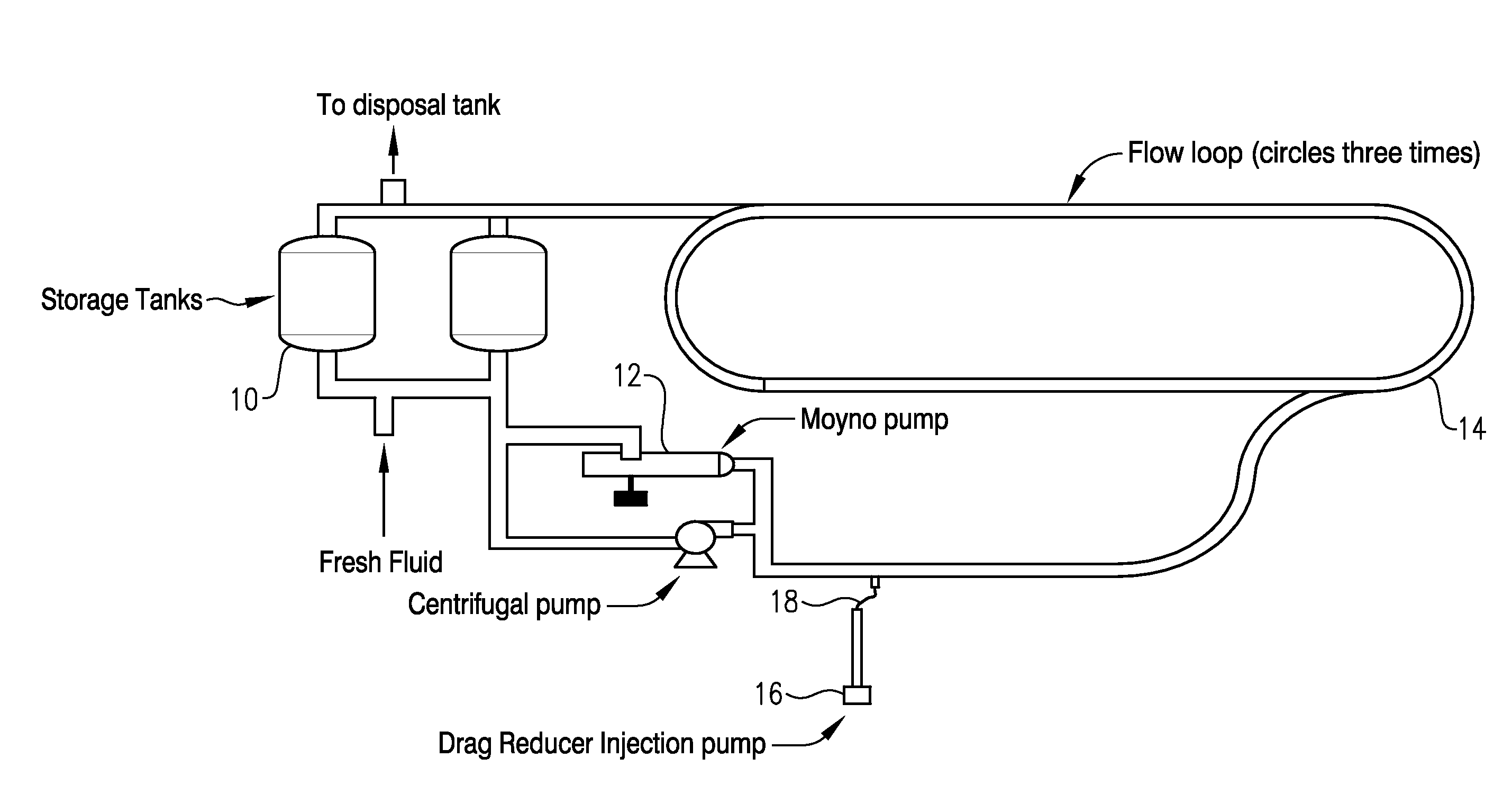
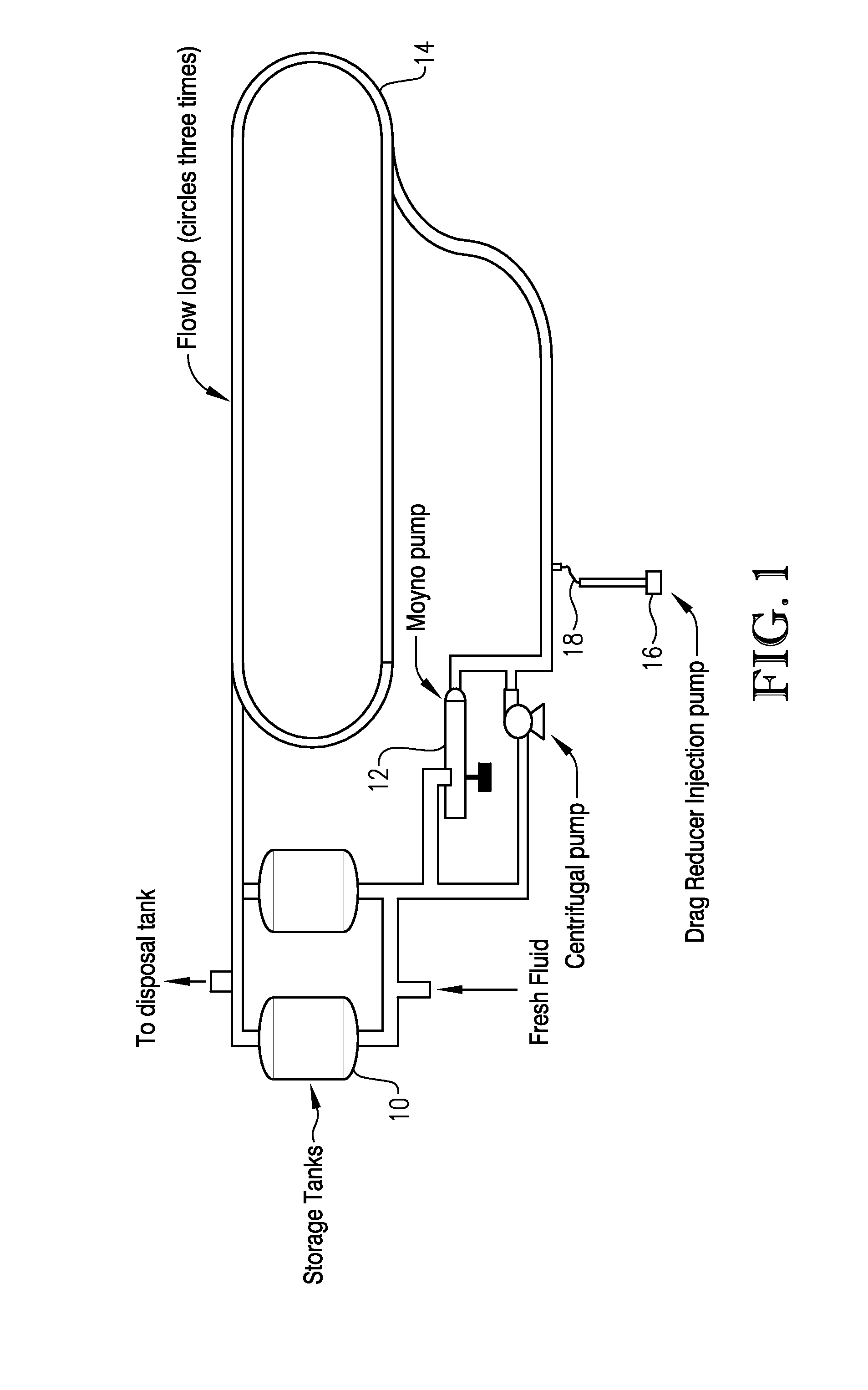
Image

Examples
example 1
Preparation of Drag Reducer Samples
Preparation of Drag Reducer A
[0070]Drag Reducer A was prepared by emulsion polymerization employing the following procedure. Polymerization was performed in a 185-gallon stainless steel, jacketed reactor with a mechanical stirrer, thermocouple, feed ports, and nitrogen inlets / outlets. The reactor was charged with 440 lbs of monomer (2-ethylhexyl methacrylate), 567.9 lbs of de-ionized water, 41.4 lbs of Polystep B-5 (surfactant, available from Stepan Company of Northfield, Ill.), 44 lbs of Tergitol 15-S-7 (surfactant, available from Dow Chemical Company of Midland, Mich.), 1.24 lbs of potassium phosphate monobasic (pH buffer), 0.97 lbs of potassium phosphate dibasic (pH buffer), and 33.2 grams of ammonium persulfate, (NH4)2S2O8 (oxidizer).
[0071]The monomer and water mixture was agitated at 110 rpm while being purged with nitrogen to remove any traces of oxygen in the reactor and was cooled to about 41° F. The two surfactants were added and the agita...
example 2
Determinations of Percent Drag Reduction
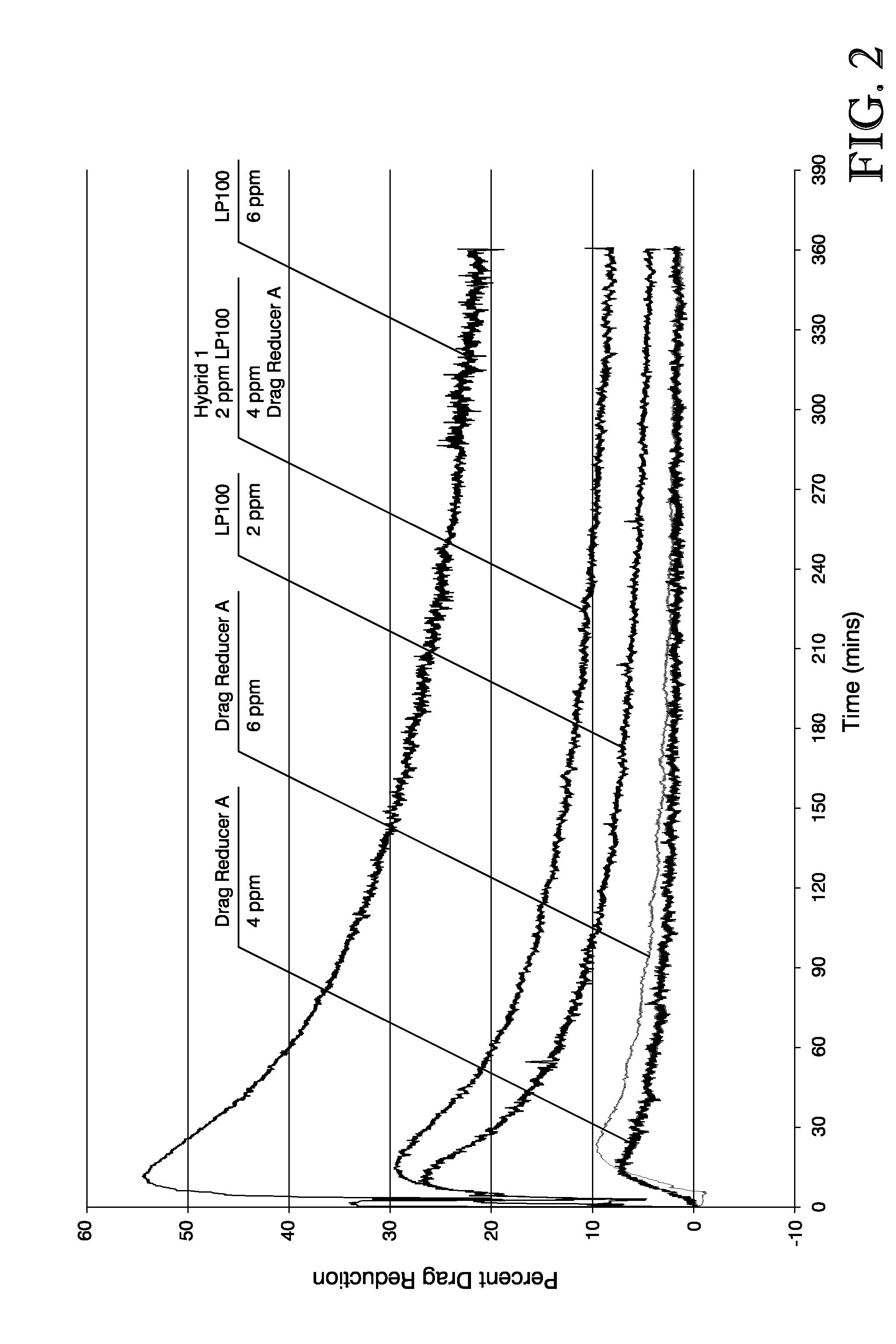
[0079]Eight tests were performed employing various concentrations of the drag reducers described in Example 1. Table 1 describes the sample compositions employed in each of the eight tests.
TABLE 1Sample CompositionsTestPolymer Concentration inNumberProductDiesel (parts per million)1LP 10022LP 10063Drag Reducer A44Drag Reducer A65Drag Reducer B46Drag Reducer B67Hybrid 1 6*8Hybrid 2 6**The 6 ppm total polymer concentration in the flow loop diesel for the Hybrid 1 test consisted of an equivalent of 2 ppm of the polymer found in LP 100 and an equivalent of 4 ppm of the polymer found in Drag Reducer A. Likewise, the 6 ppm total polymer concentration in the flow loop diesel for the Hybrid 2 test consisted of an equivalent of 2 ppm of the polymer found in LP 100 and an equivalent of 4 ppm of the polymer found in Drag Reducer B.
[0080]Each of the eight tests was performed according to the Test Method described above in order to determine the percent dr...
PUM
| Property | Measurement | Unit |
|---|---|---|
| Temperature | aaaaa | aaaaa |
| Length | aaaaa | aaaaa |
| Length | aaaaa | aaaaa |
Abstract
Description
Claims
Application Information
 - R&D
- Intellectual Property
- Life Sciences
- Materials
- Tech Scout
- Unparalleled Data Quality
- Higher Quality Content
- 60% Fewer Hallucinations
Browse by: Latest US Patents, China's latest patents, Technical Efficacy Thesaurus, Application Domain, Technology Topic, Popular Technical Reports.
© 2025 PatSnap. All rights reserved.Legal|Privacy policy|Modern Slavery Act Transparency Statement|Sitemap|About US| Contact US: help@patsnap.com