Gas Leak Detection Device and Gas Leak Detection Method
a technology of leak detection device and gas leak detection method, which is applied in the measurement of fluid loss/gain rate, fluid tightness measurement, instruments, etc., can solve the problems of not being able to easily correspond external temperature and gas pressure to each other, and not considering a change in gas temperature, etc., to achieve high accuracy
- Summary
- Abstract
- Description
- Claims
- Application Information
AI Technical Summary
Benefits of technology
Problems solved by technology
Method used
Image
Examples
first example
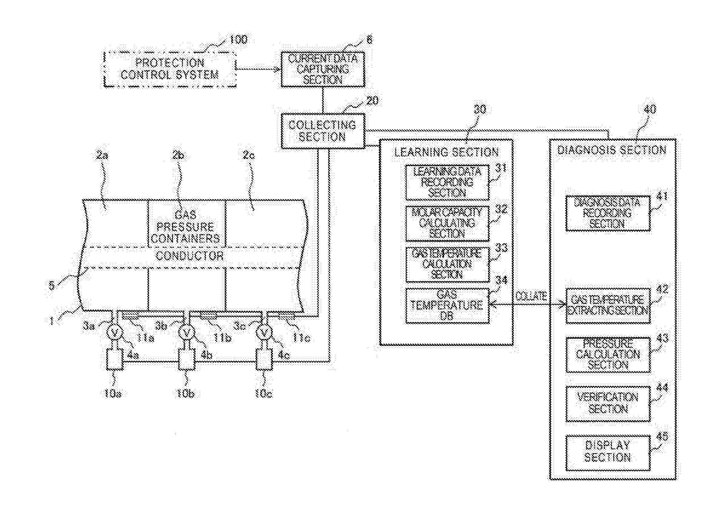
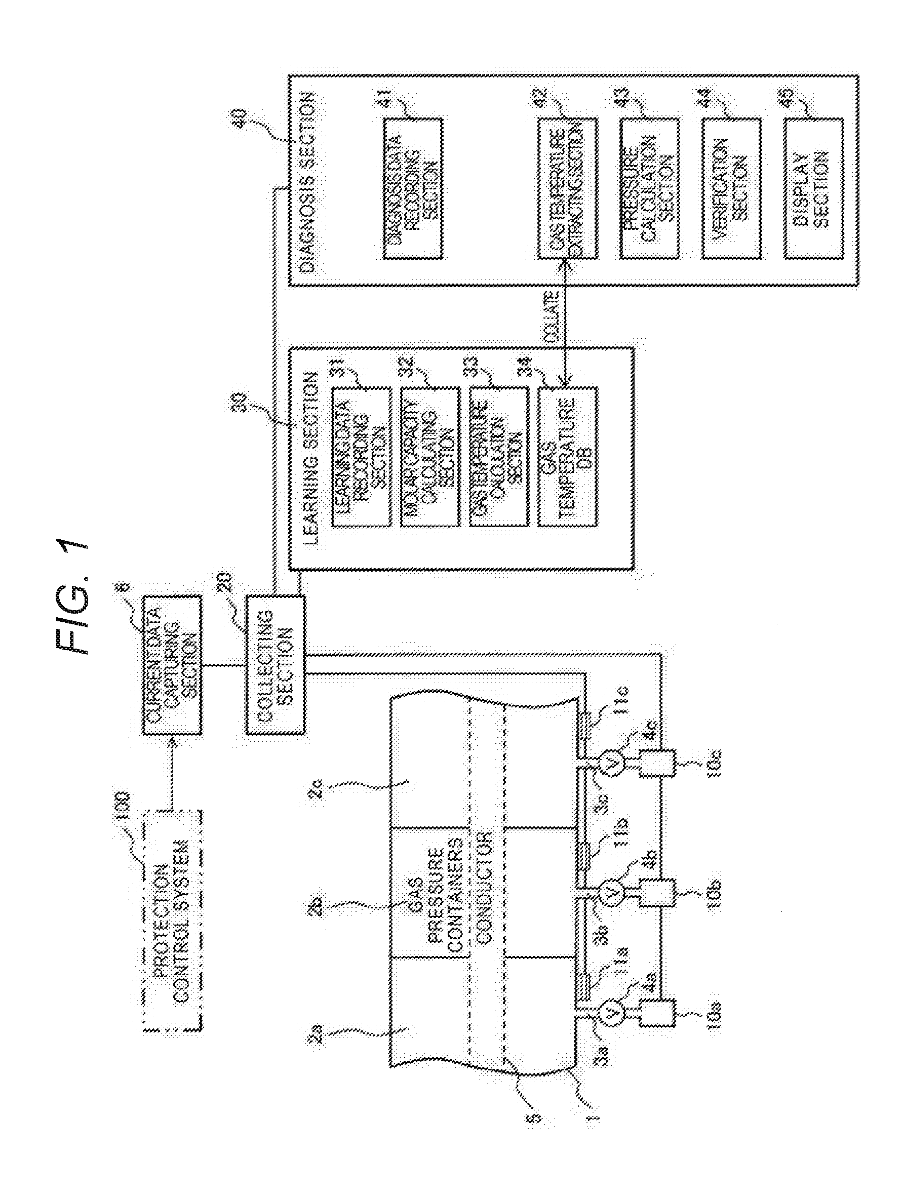
[0032]FIG. 1 is a configuration diagram of a gas leak detection device according to a first example of the invention.
[0033]As illustrated in FIG. 1, the gas insulation switching device 1 is configured with a plurality of gas pressure containers 2a to 2c which are linked, and a conductor 5 penetrates the center thereof in a coaxial direction of the gas pressure containers 2a to 2c (a direction where the gas pressure containers 2a to 2c are arranged). A current data capturing section 6 captures a current value flowing in the conductor 5 from a protection control system 100 of an electric power substation. The current data capturing section 6 is connected to the protection control system 100 through a wired (communication wire) or wireless communication system.
[0034]In the gas pressure containers 2a to 2c, insulating gas SF6 of a predetermined gas pressure is sealed. Insulating gas such as SF6 has high electric insulation properties. In order to perform monitoring of a gas pressure in ...
second example
[0082]FIG. 16 illustrates a second example of the invention. FIG. 16 is a configuration diagram of the gas leak detection device according to the second example of the invention.
[0083]A second example is different from the first example in the way that a current sensor 7 and a converter 8 are provided in order to obtain information of a current flowing in the conductor 5. The converter 8 is installed in the conductor 5, and is connected to the current sensor 7 by reducing a large current of a primary side flowing in the conductor 5 to a current of a secondary side. For example, in a case in which a current conversion ratio of a primary current and a secondary current is 400, the primary current 4000 A flowing in the conductor is converted to the secondary current 10 A and is input to the current sensor 7.
[0084]The current sensor 7 and the converter 8 constitute the current data capturing section 6 which captures a current value flowing in the conductor 5 to the learning section 30 a...
PUM
 Abstract
Description
Claims
Application Information
 - R&D
- Intellectual Property
- Life Sciences
- Materials
- Tech Scout
- Unparalleled Data Quality
- Higher Quality Content
- 60% Fewer Hallucinations
Browse by: Latest US Patents, China's latest patents, Technical Efficacy Thesaurus, Application Domain, Technology Topic, Popular Technical Reports.
© 2025 PatSnap. All rights reserved.Legal|Privacy policy|Modern Slavery Act Transparency Statement|Sitemap|About US| Contact US: help@patsnap.com


