
Sensor package

a technology of sensor and package, applied in the field of sensor package, can solve the problems of degrading affecting the accuracy of pressure detection, and leaking of residual air, so as to maintain the accuracy of temperature characteristics and pressure detection, the effect of suppressing the effect of the surrounding environment and reducing the degradation of temperature characteristics

Active Publication Date: 2017-02-02
ALPS ALPINE CO LTD
View PDF3 Cites 4 Cited by
  • Summary
  • Abstract
  • Description
  • Claims
  • Application Information

AI Technical Summary

Benefits of technology

The patent text describes a sensor package that can prevent the effects of its surrounding environment on temperature and pressure detection. It can suppress the need for a large and complicated calibration device and avoid making the lead frame or region around it complicated.

Problems solved by technology

Such residual air may leak as air bubbles through the gap or the interface due to a variation in pressure during detection.
This may degrade accuracy of pressure detection.
Furthermore, the gap between the lead frame or the conductive portion and the resin may become an air leakage path from the outside to the inside of the pressure sensor device.
This degrades the accuracy of pressure detection.
However, in the case where the resin that covers the lead frame or the conductive portion is in contact with a pressure sensor that detects pressure, when the temperature of the resin varies due to a variation in temperature of a region around a device or a variation in temperature of the lead frame, accuracy of temperature characteristics of the pressure sensor may be degraded because the pressure sensor in contact with the resin is also affected by a surrounding environment.
Furthermore, in many cases a resin having a high Young's modulus has high stress while hardening.
Thus, selectable materials are limited, and accordingly, reduction of cost is difficult.
Thus, it is required that a large and complex calibration device be prepared.
This leads to a problem in that a routing pattern of the lead frame or the conductive portion and the structure around the routing pattern become complex.
Thus, the air in the gap and the interface between the main housing and the lead frame is unlikely to expand.
Thus, variations in temperature around the device and the lead frame are unlikely to be transmitted to the pressure sensor.

Method used


Image

  • Sensor package
  • Sensor package
  • Sensor package

Examples


Embodiment Construction

[0048]A sensor package according to embodiments of the present invention will be described in detail below with reference to the drawings. The following description is intended to convey a thorough understanding of the embodiments described by providing a number of specific embodiments and details involving a sensor package. It should be appreciated, however, that the present invention is not limited to these specific embodiments and details, which are exemplary only. It is further understood that one possessing ordinary skill in the art, in light of known systems and methods, would appreciate the use of the invention for its intended purposes and benefits in any number of alternative embodiments, depending on specific design and other needs.

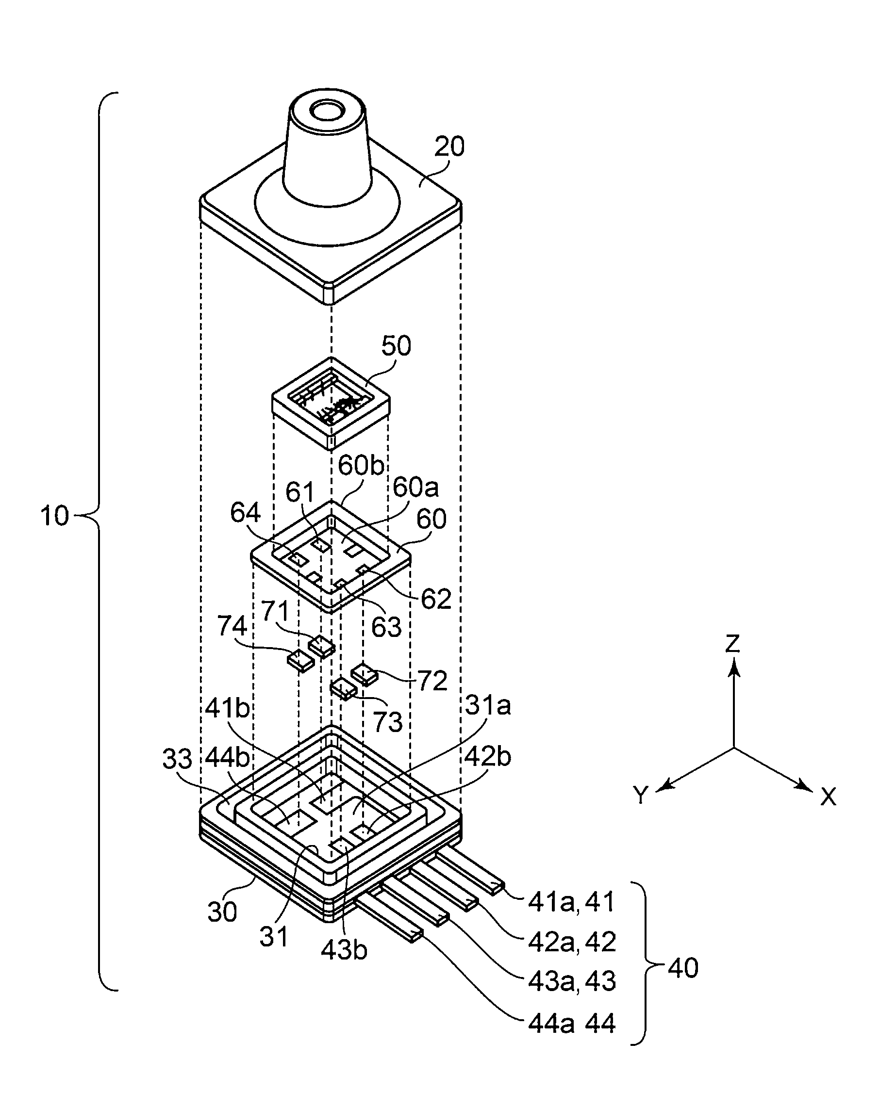
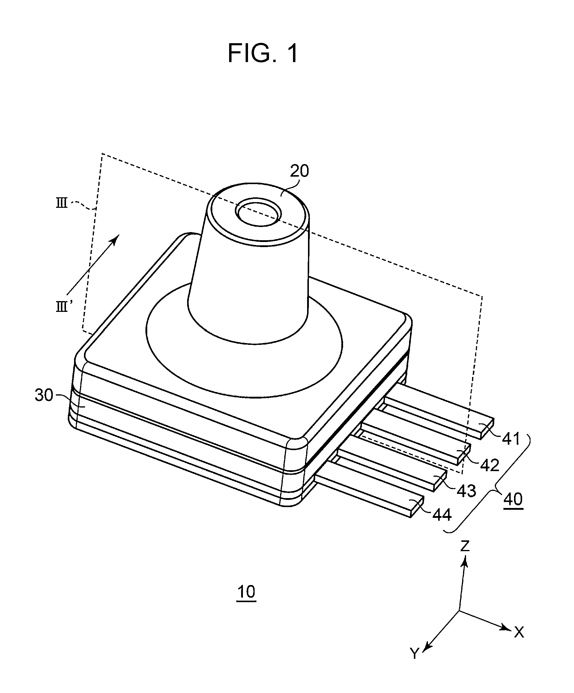
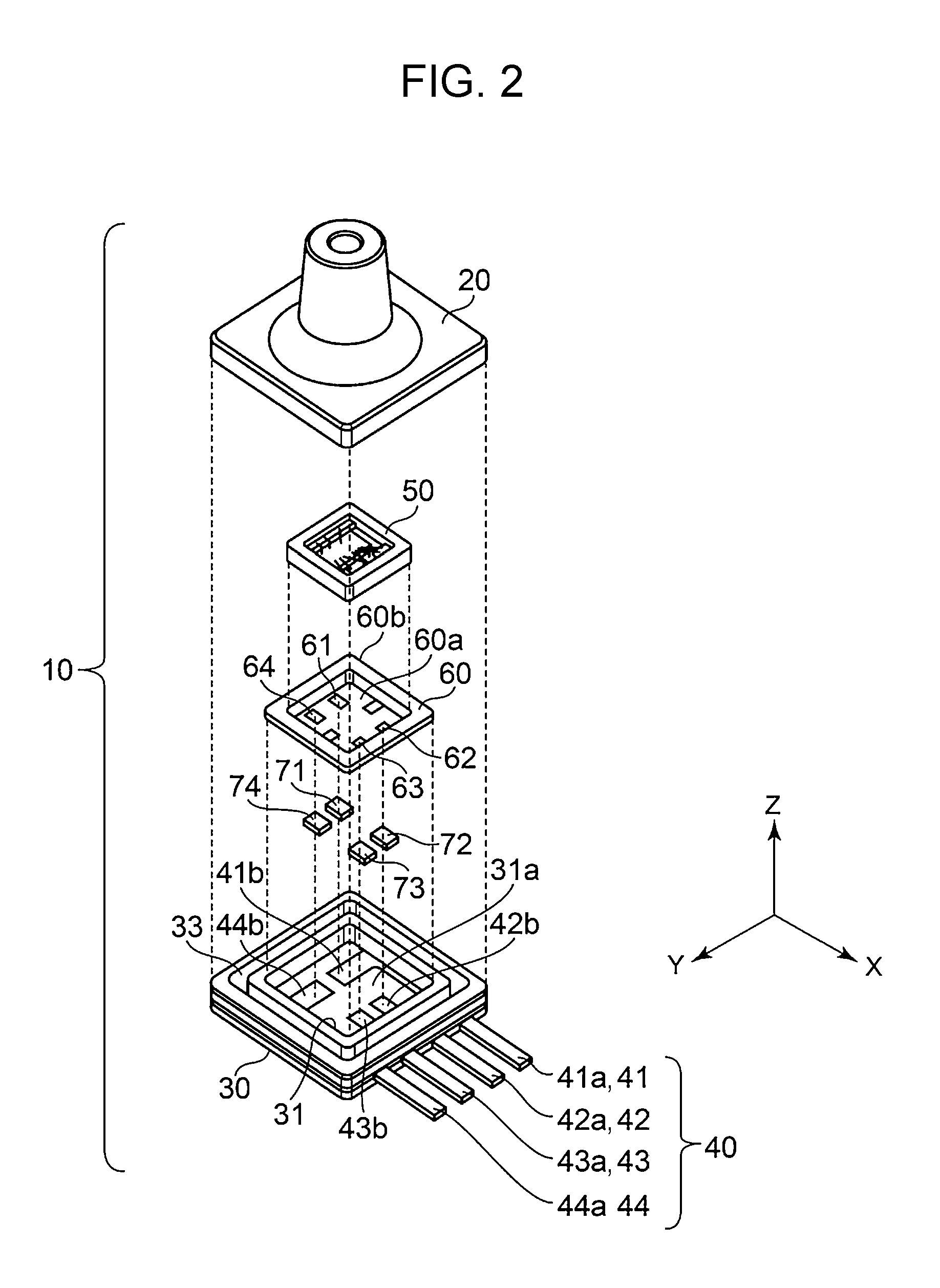
[0049]FIG. 1 is a perspective view of a structure of a sensor package 10 according to an example embodiment of the disclosure. FIG. 2 is an exploded perspective view of the structure of the sensor package 10. FIG. 3 is a sectional view of the st...


PUM


Abstract

A sensor package includes a pressure sensor, a computation unit that performs specified computation in accordance with a result of detection performed by the pressure sensor, a lead frame through which a result of computation performed by the computation unit is output to an outside, a main housing that is formed of resin and that holds the lead frame, and a sensor housing that is formed of ceramic and that has an inner space in which the pressure sensor is disposed. The pressure sensor is disposed in the main housing using the sensor housing.

Description

CLAIM OF PRIORITY[0001]This application contains subject matter related to and claims the benefit of Japanese Patent Application No. 2015-150410 filed on Jul. 30, 2015, the entire contents of which is incorporated herein by reference.BACKGROUND OF THE DISCLOSURE[0002]1. Field of the Disclosure[0003]The present disclosure relates to a sensor package used for detecting pressure in automobiles, industrial machines, and so forth.[0004]2. Description of the Related Art[0005]A temperature sensor-integrated pressure sensor device described in Japanese Patent No. 3870918 includes a pressure sensor element, a lead frame electrically connected to this pressure sensor element, a connector pin electrically connected to this lead frame, and a pressure introduction hole through which a medium the pressure of which is to be measured is introduced. The pressure sensor element and the lead frame are enclosed by mold resin.[0006]A semiconductor pressure sensor device described in Japanese Patent No. ...

Claims


Application Information

Patent Timeline
IPC IPC(8): G01L19/00G01L19/04
CPCG01L19/04G01L19/0084G01L9/0051G01L9/0072G01L9/025G01L9/125G01L19/0038G01L19/143G01L19/0076
Inventor OKAWA, HISANOBUSEJIMO, KAZUSHIGEKERA, CHIAKIYAMAUCHI, SHIGEAKI
Owner ALPS ALPINE CO LTD
Learn More