
Process Design For Acid Gas Removal

a technology of process design and acid gas, applied in the field of systems and methods, can solve the problems of low acid gas system total cost, high uncertainty in the actual long-term production profile of the gas field and acid gas composition profile, and limited acid gas removal volume of traditional acid gas removal technology such as amines and physical solvents, and achieve the effect of maximum efficiency

Active Publication Date: 2017-01-19
CAMERON SOLUTIONS
View PDF9 Cites 6 Cited by
  • Summary
  • Abstract
  • Description
  • Claims
  • Application Information

AI Technical Summary

Benefits of technology

The patent describes a system and process for removing acid gas (CO2 and H2S) from gas using membrane permeation. The system can handle a wide range of inlet gas compositions while maintaining the quality of the non-permeate gas. The system uses primary and secondary membrane units, which can be adjusted to different CO2 concentrations to achieve maximum efficiency. This design allows end users to access a greater variety of gas supply sources that would be unavailable without another acid gas removal phase expansion. Overall, the system and process provide a cost-effective solution for acid gas removal while maintaining gas quality.

Problems solved by technology

The total volume of acid gas removed by traditional acid gas removal technologies such as amines and physical solvents is limited by size of the contactors and the initial installed volume of solvent and the regeneration rates.
The actual long-term production profile of the gas field and acid gas composition profile is often highly uncertain at the time that the initial acid gas processing equipment is installed upstream of the LNG, power plant of the pipeline.
In efforts to keep the total cost of the acid gas system low, the acid gas removal systems are often not initially designed to handle inlet gas at the high range of inlet acid gas compositions over the field production lifetime.
Therefore, new acid gas processing equipment and associated compression are typically added in phases (e.g., Phase 1, Phase 2, . . . Phase N), which adds considerable capital cost to operations.

Method used


Image

  • Process Design For Acid Gas Removal
  • Process Design For Acid Gas Removal
  • Process Design For Acid Gas Removal

Examples


Embodiment Construction

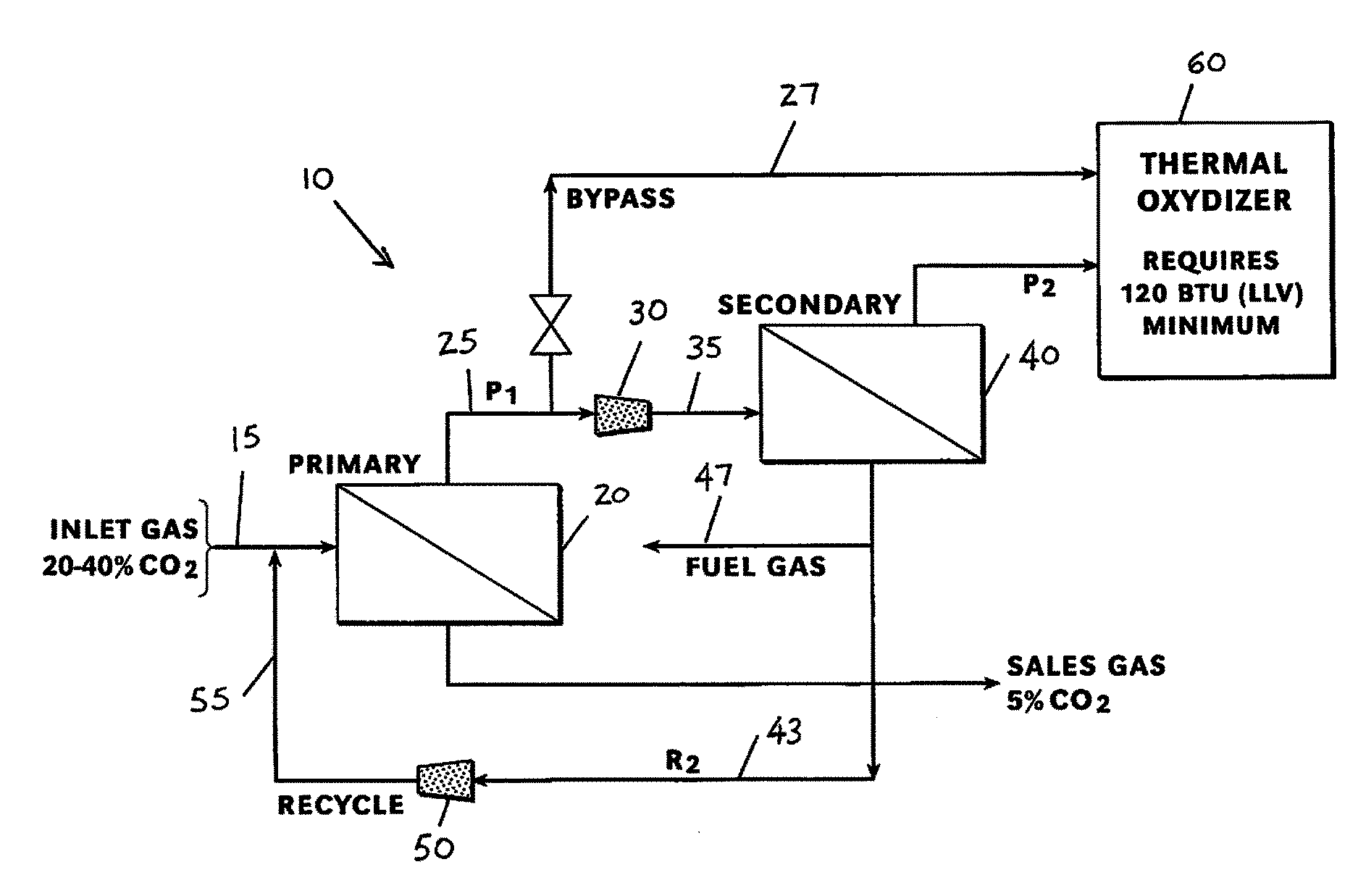
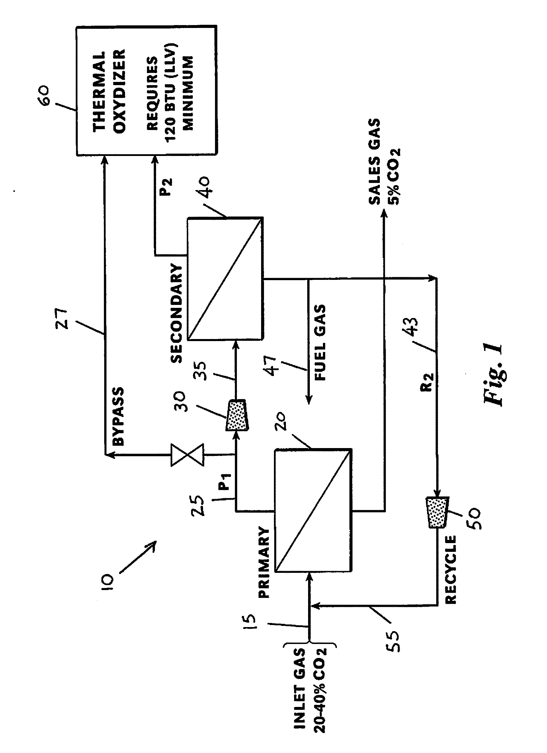
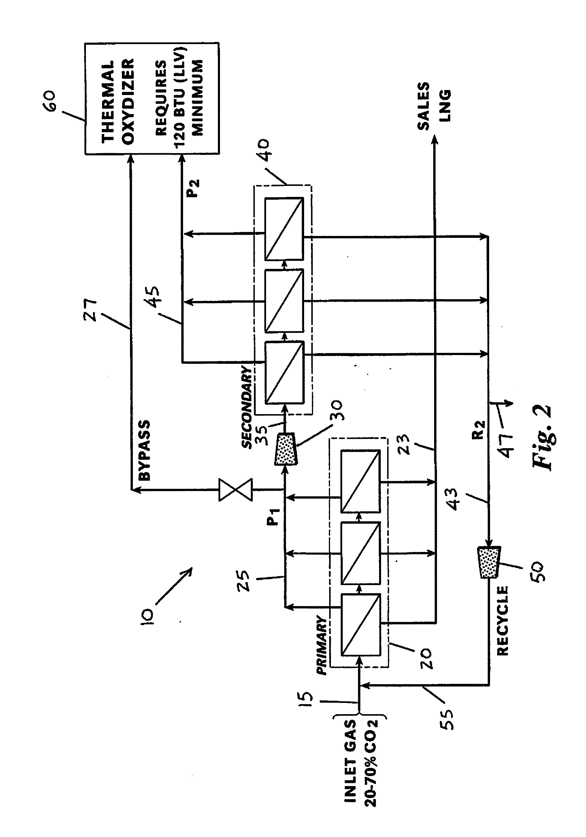
[0044]Referring to FIGS. 1 and 2, a preferred embodiments of a system and process 10 for acid gas removal are arranged to receive an inlet natural gas stream 15 from one or more natural gas wells or fields. Although the inlet natural gas stream 15 increases in acid gas concentration over time, the system and process 10 accommodate this increase without additional equipment being added and without relying upon any increase in downstream amines or physical solvents. The glassy polymer membranes used in the system and process 10 are selected so removal duty efficiency increases as acid gas concentration increase. Designing the system and process to handle about a 15% increase in acid gas concentrations over initial conditions effectively treats acid gas concentrations well above that 15% increase, thereby eliminating the need for additional equipment or additional downstream amines or physical solvents.

[0045]In one preferred embodiment, the glassy polymer membranes are arranged in a pr...


PUM

PropertyMeasurementUnit
Fractionaaaaaaaaaa
Fractionaaaaaaaaaa
Efficiencyaaaaaaaaaa

Abstract

A membrane permeation system and process accommodates varying acid gas inlet concentrations over time while utilizing only the initially installed equipment and still maintaining the non-permeate gas specification. The system and process provide flexibility to operate efficiently over a wide range of inlet CO2 concentrations by adjustments to primary permeate, secondary permeate, and recycle gas operations. The glassy polymer membrane devices used in the system and process are selected so removal duty efficiency increases as acid gas concentration increase. Designing the system and process to handle about a 15% increase in acid gas concentrations over initial conditions effectively treats acid gas concentrations well above that 15% increase, thereby eliminating the need for additional equipment or for additional downstream amines and physical solvents.

Description

CROSS-REFERENCE TO RELATED APPLICATIONS[0001]The present application claims priority to U.S. Provisional Patent Application No. 62 / 193,152 filed on Jul. 16, 2015, which is incorporated herein by reference.BACKGROUND OF THE INVENTION[0002]This invention relates to systems and methods used to remove acid gas (CO2 and H2S) from a natural gas stream. More specifically, the invention relates to systems and methods designed to remove those acid gases by membrane permeation and not using amines or physical solvents.[0003]The total volume of acid gas removed by traditional acid gas removal technologies such as amines and physical solvents is limited by size of the contactors and the initial installed volume of solvent and the regeneration rates. Because of this, if acid gas removal requirements increase—due to higher acid gas concentrations in the inlet gas—by more than the original design margin (typically between 5% and 10% higher than design basis), more equipment must be added to proces...

Claims


Application Information

Patent Timeline
IPC IPC(8): B01D53/22C10L3/10B01D71/16B01D63/04B01D63/12
CPCB01D53/226C10L2290/30B01D63/04B01D63/12B01D71/16C10L3/103C10L3/104B01D2053/224B01D2053/221B01D2313/243B01D2317/025B01D2325/20C10L2290/548C10L2290/10B01D53/229C10L2290/562C10L3/102C10L2290/565C10L2290/58C10L2290/46
Inventor PETERS, RICHARD D.
Owner CAMERON SOLUTIONS
Learn More