
Image block selection for efficient time-limited decoding

a time-limited decoding and image block technology, applied in image enhancement, instruments, sensing by electromagnetic radiation, etc., can solve the problems of short interval, time constraint is a particular challenge, and the search of the full extent of such a composite image in search of decodable indicia is typically too time-consuming

Active Publication Date: 2016-12-15
DIGIMARC CORP
View PDF13 Cites 30 Cited by
  • Summary
  • Abstract
  • Description
  • Claims
  • Application Information

AI Technical Summary

Benefits of technology

The patent text describes a method for improving the processing speed and accuracy of camera-based retail scanning systems. The method involves preparing an ordered listing of processing parameters that are used to decoder indicia captured by the scanning system. The listing is derived from reference scanner images that are analyzed exhaustively. The method allows the scanning system to optimize its behavior based on the habits of different operators and shoppers. The technical effect of this method is faster and more accurate decoding of indicia, leading to improved efficiency and productivity in retail scanning.

Problems solved by technology

If real-time operation is to be achieved, such systems can only allocate a short interval to process each image.
This time constraint is a particular challenge because product-identifying indicia (e.g., a barcode or watermark data) may appear anywhere in the captured frames.
Searching the full extent of such a composite image in search of a decodable indicia is typically too time consuming.
Yet another complication is that the pose at which any indicia is captured is unknown.
The indicia may be unrecognizable due to the perspective distortion introduced by the pose.
A variety of brute-force compensations can be applied to try and counter-act possible distortions to improve detection, but only a limited number of such compensations can be tried in the limited period available.
This is beyond the capabilities of the processing hardware commonly provided in retail scanners, and associated point of sale terminals.

Method used


Image

  • Image block selection for efficient time-limited decoding
  • Image block selection for efficient time-limited decoding
  • Image block selection for efficient time-limited decoding

Examples


Embodiment Construction

[0032]For expository convenience, this description is focused on identification of products by decoding digital watermark data. However, it should be recognized that the same techniques are equally applicable to extraction of product identifying data otherwise, such as by barcode decoding, optical character recognition, or by image fingerprint extraction / matching.

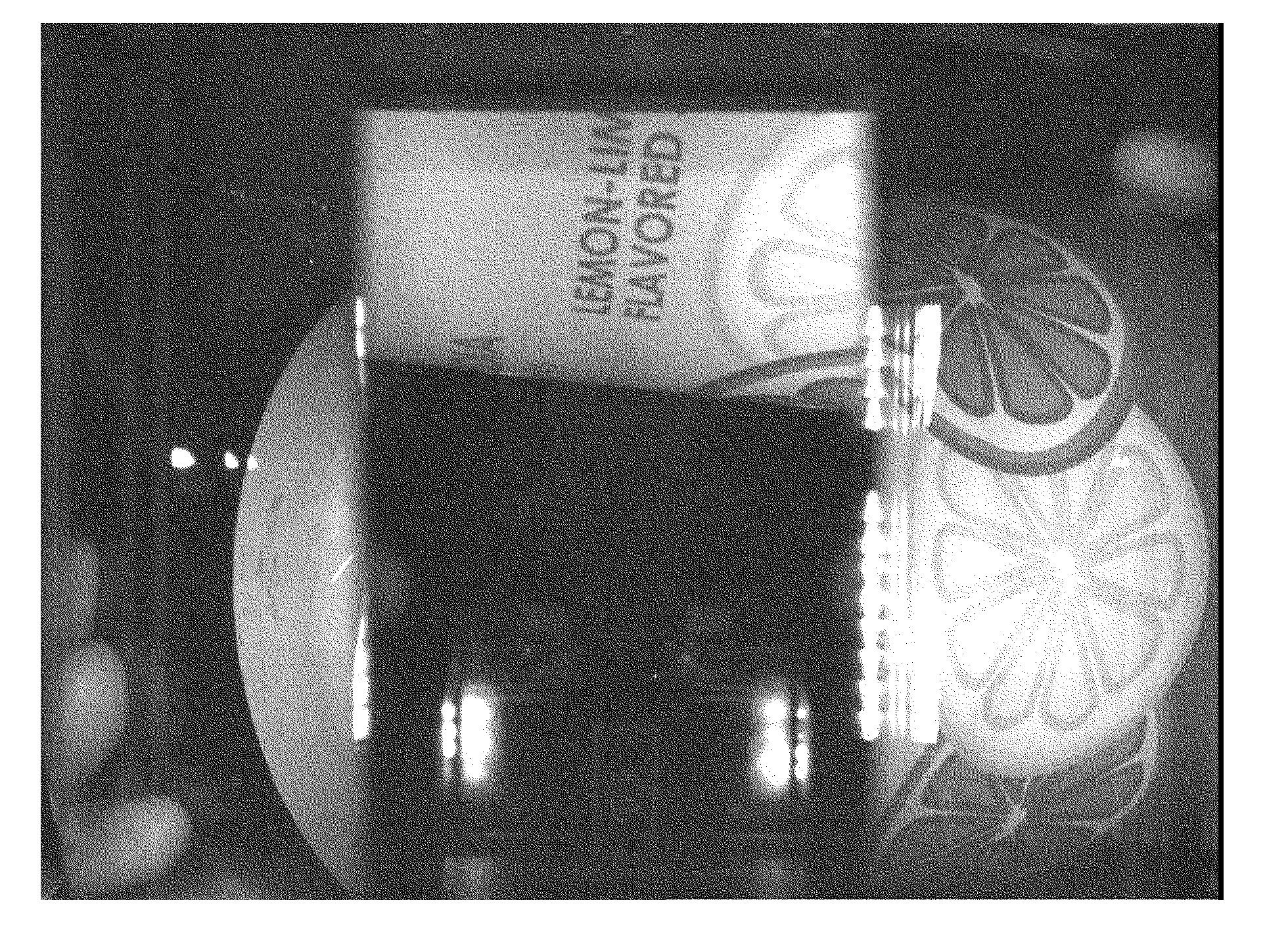
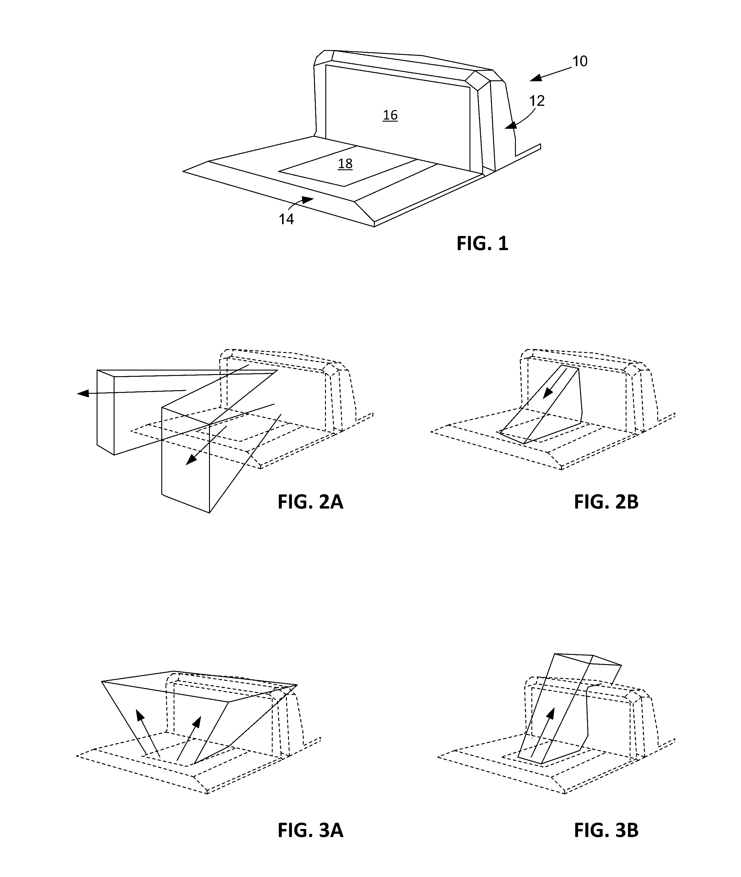
[0033]Referring to FIG. 1, an illustrative retail scanner 10 includes a vertically-extending tower portion 12, and a horizontally-extending platter portion 14. Each portion includes a window 16, 18 through which one or more camera systems captures imagery of items presented for scanning.

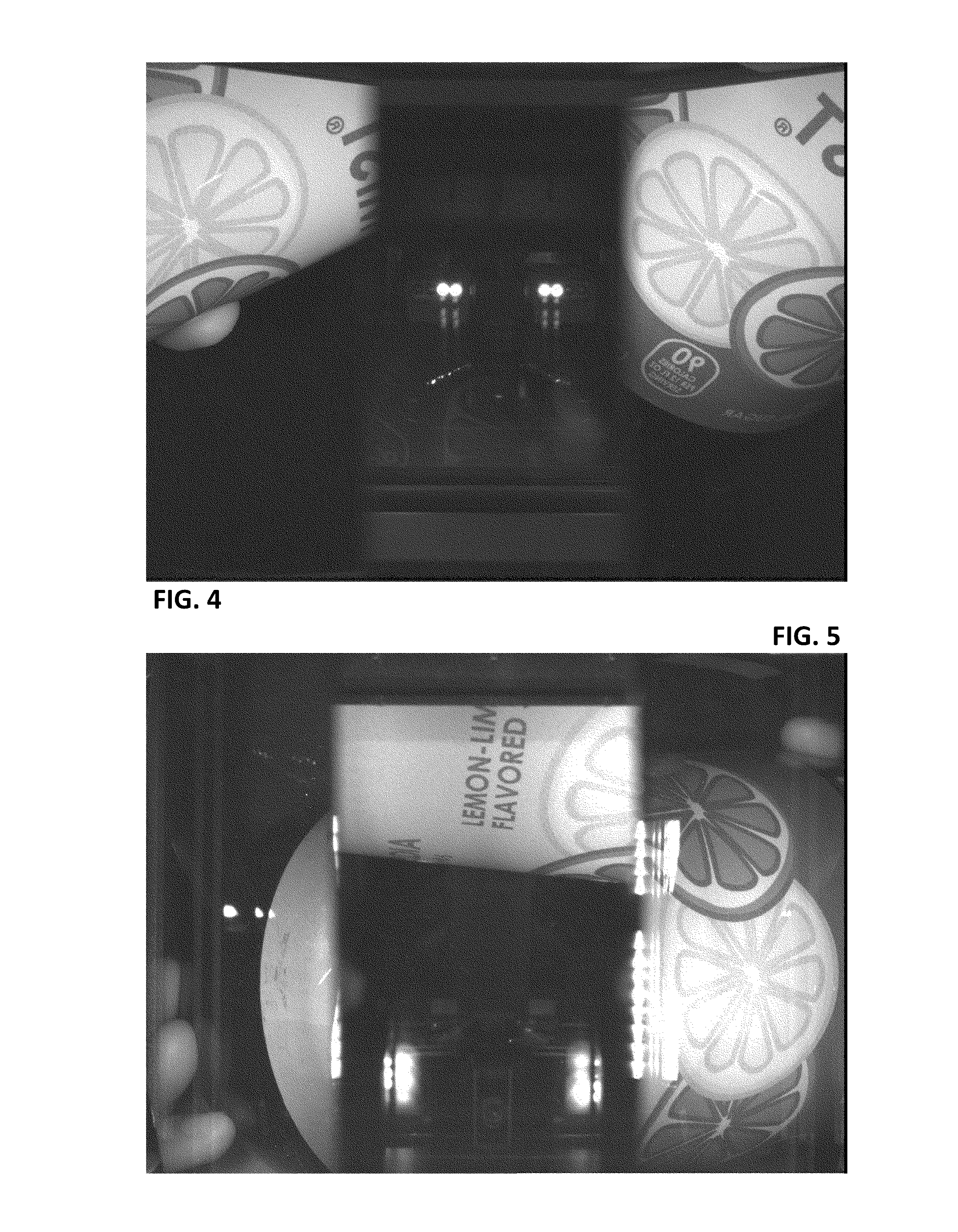
[0034]In the FIG. 1 scanner, an arrangement of mirrors projects several different views of the retail product onto different parts of a camera sensor in the tower portion. Likewise for the platter portion. In particular, the optics arrangement in the tower captures two views looking out horizontally from the mid-height of the window 16, at a...


PUM


Abstract

Object recognition by point-of-sale camera systems is aided by first removing perspective distortion. Yet pose of the object—relative to the system—depends on actions of the operator, and is usually unknown. Multiple trial counter-distortions to remove perspective distortion can be attempted, but the number of such trials is limited by the frame rate of the camera system—which limits the available processing interval. One embodiment of the present technology examines historical image data to determine counter-distortions that statistically yield best object recognition results. Similarly, the system can analyze historical data to learn what sub-parts of captured imagery most likely enable object recognition. A set-cover strategy is desirably used. In some arrangements, the system identifies different counter-distortions, and image sub-parts, that work best with different clerk- and customer-operators of the system, and processes captured imagery accordingly. A great variety of other features and arrangements are also detailed.

Description

RELATED APPLICATION DATA[0001]This application claims priority to provisional patent application 62 / 174,454, filed Jun. 11, 2015, the disclosure of which is incorporated herein by reference.BACKGROUND AND SUMMARY[0002]Camera-based retail scanning systems commonly capture between 30 and 100 frames of imagery every second. If real-time operation is to be achieved, such systems can only allocate a short interval to process each image. For example, if a system captures 60 frames each second, it can devote a maximum of 16.6 milliseconds to each image.[0003]This time constraint is a particular challenge because product-identifying indicia (e.g., a barcode or watermark data) may appear anywhere in the captured frames. Moreover, each captured image is commonly a synthesis of several different images—captured from different viewpoints by an optical arrangement including multiple mirrors. Searching the full extent of such a composite image in search of a decodable indicia is typically too tim...

Claims


Application Information

Patent Timeline
IPC IPC(8): G06K9/46G06K7/10G06T1/00G06K9/20G06T5/00G06V10/20G06V30/224
CPCG06K9/4604G06K9/20G06K7/10722G06T1/0021G06T5/002G06K7/146G06T3/00G06V30/224G06V10/247G06V10/20G06V10/464G06V30/1916G06T5/70G06T2207/20081G06F18/217
Inventor EVANS, ERIC D.FILLER, TOMAS
Owner DIGIMARC CORP
Learn More