Eureka AIR delivers breakthrough ideas for toughest innovation challenges, trusted by R&D personnel around the world.

Method and device for predictive control of agricultural vehicle systems

a technology for agricultural vehicles and predictive control, applied in the direction of instruments, analogue processes for specific applications, electric/magnetic computing, etc., can solve the problems of insufficient prediction accuracy, referencing data must be available, and it is difficult to have an automated system that is as efficient as an experienced operator

Active Publication Date: 2013-07-18
BLUE LEAF I P INC
View PDF40 Cites 42 Cited by
  • Summary
  • Abstract
  • Description
  • Claims
  • Application Information

AI Technical Summary

Benefits of technology

The present invention provides a method and device for controlling an agricultural vehicle system. The method uses a field model to predict the values of various fields characteristic, such as soil moisture or crop yield, based on the location of the agricultural vehicle system. This allows for better control of the agricultural vehicle system, even without prior data from previous passes. The method also includes predicting the future field characteristics based on the current values, and updating the field model as new measurements become available. The agricultural vehicle system can thus anticipate changes in field characteristics and maintain consistent performance throughout the field over time.

Problems solved by technology

At present, automatic control systems do not have this upfront information, which makes it hard to have an automated system that is as efficient as an experienced operator.
It is a disadvantage of this system that the geo-referencing data has to be available, either from a previous pass with the same vehicle over the field (geo-referencing data stored when vehicle passed over the field during a previous season for example), or from a pass with another vehicle over the same field (in which case the geo-referencing data needs to be transferred from one vehicle to another).
It is a disadvantage of the model used in DE19528663 that predictions are not accurate enough.

Method used


Image

  • Method and device for predictive control of agricultural vehicle systems
  • Method and device for predictive control of agricultural vehicle systems
  • Method and device for predictive control of agricultural vehicle systems

Examples


example

[0113]In the following, a few schematic examples are illustrated of how a model in accordance with embodiments of the present invention may be applied to a grid overlaying a field.

[0114]As an example, a field 90 to be worked is provided, e.g. overlaid, with a grid 91, e.g. a grid of n×m elements with each a predetermined resolution of e.g. 5 meter by 5 meter, as illustrated in FIG. 8. Over time, during a time period during which an agricultural vehicle system works the field, the elements of the grid 91, in accordance with embodiments of the present invention, are filled with values representing a field characteristic. The field characteristic may for example be farmland slope, but the invention is not limited thereto. In accordance with embodiments of the present invention, when an agricultural vehicle system passes over the elements, values for the field characteristic are determined by measurement. At the same time, values representing the field characteristic for surrounding ele...


PUM


Abstract

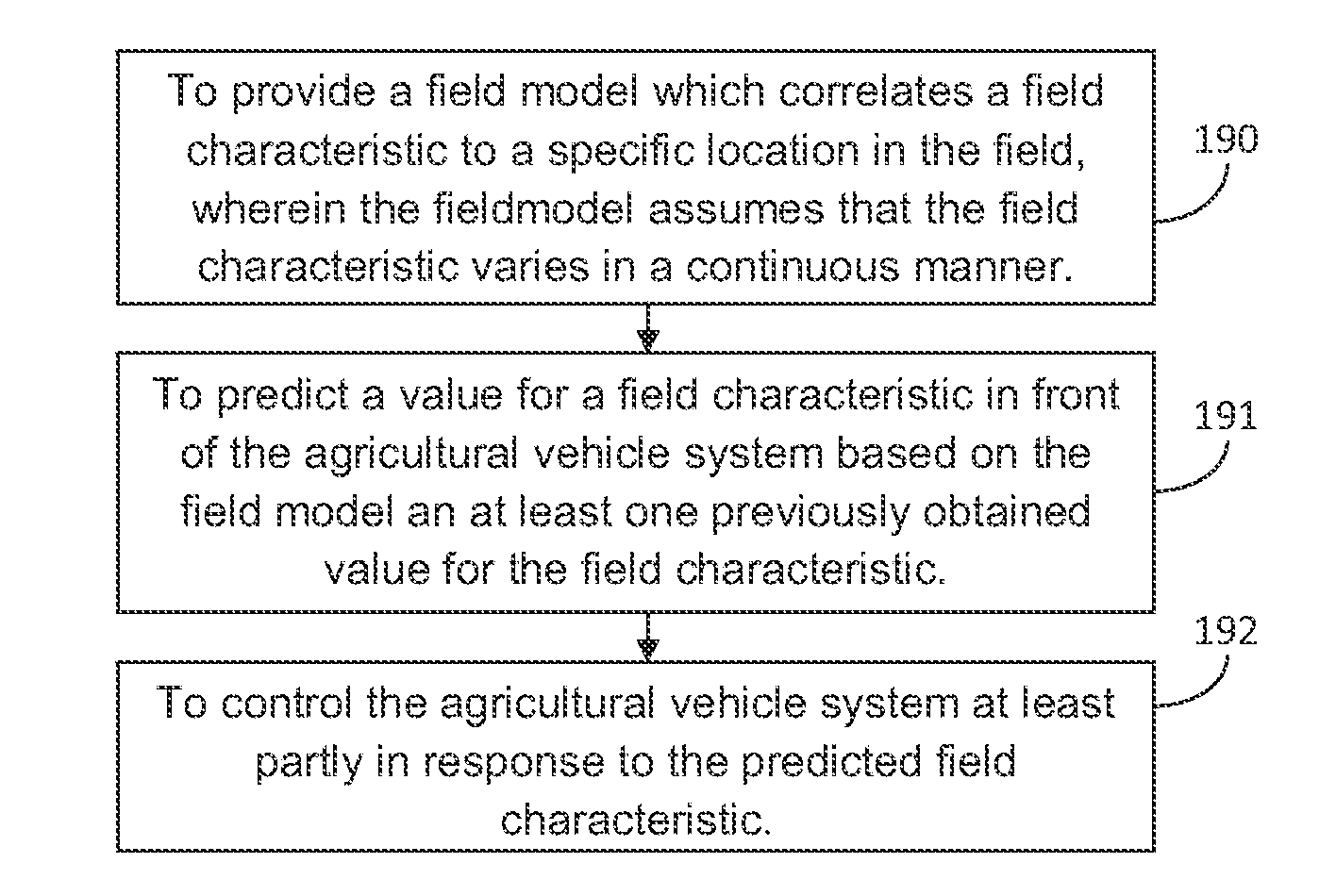
The present invention provides a method for controlling an agricultural vehicle system when moving along a course of travel over a field. The method comprises:providing (190) a field model correlating a field characteristic, e.g. a farmland condition such as farmland slope, or a crop condition such as crop density or moisture, to a specific location in the field, for example indicated by x and y coordinates;from the field model and at least one previously obtained value for the field characteristic, predicting (191) a value for the field characteristic in front of the agricultural vehicle system thus obtaining an anticipated field characteristic, and;controlling (192) the agricultural vehicle system at least partly in response to the anticipated field characteristic.In accordance with embodiments of the present invention, providing (190) a field model correlating a field characteristic to a specific location in the field includes assuming that the field characteristic varies in a continuous manner.

Description

FIELD OF THE INVENTION[0001]The present invention relates generally to control of agricultural vehicle systems. In particular, the present invention relates to methods and devices for, based on location coordinates and field characteristics collected from an already worked area during a previous pass, predicting which working conditions the agricultural vehicle system will encounter while working a next pass in the field.BACKGROUND OF THE INVENTION[0002]In recent years control systems have been used to alleviate the task of operators of agricultural vehicle systems. Automation allows an operator to concentrate on other tasks such as coordinating transport. Moreover, such control systems guarantee constant performance throughout the day whereas an operator gets tired.[0003]Control systems on agricultural vehicle systems can only take into account information collected by the agricultural vehicle system at a time t in the past. However, an experienced operator looks ahead and estimate...

Claims


Application Information

Patent Timeline
Patent Type & Authority Applications(United States)
IPC IPC(8): A01B69/00
CPCA01B69/007A01D75/28A01D41/127A01B69/00
Inventor MISSOTTEN, BART M.A.COEN, TOM
Owner BLUE LEAF I P INC
Why Eureka
Eureka Blog
Learn More