
Neurosurgical instruments

a neurosurgical and instrument technology, applied in the direction of surgery, guide wires, catheters, etc., can solve the problems of reducing the delivery to the tissue, affecting the delivery of drugs through the extracellular space, and reducing the delivery of infusate directly into the cerebrospinal fluid

Active Publication Date: 2016-12-01
RENISHAW PLC
View PDF9 Cites 26 Cited by
  • Summary
  • Abstract
  • Description
  • Claims
  • Application Information

AI Technical Summary

Benefits of technology

The present invention provides a catheter assembly for insertion into the brain, which includes first and second lengths of tubing. The first length is made of a stiff material, while the second length is made of a flexible material that has a hardness of less than 50 Rockwell E. The second length may be a separate length of tubing, or it may be part of the first length of tubing. The assembly may also include an additional length of tubing that creates an annular gap between the first and second lengths. The first and second lengths of tubing may have different hardness values. The first length of tubing extends further than the additional length of tubing. The second aspect of the invention provides a catheter assembly for insertion into the brain, which includes inner and outer concentric layers with an annular gap between them. The inner and outer layers are both stiff. The outer layer has a module of elasticity of greater than 30 GPa. The inner layer is made of fused silica, and the outer layer is made of fused silica or stainless steel. The inner layer has a polyimide coating.

Problems solved by technology

However, at high flow rates, the solution can flow back up the catheter shaft leaking to the surface and reducing delivery to the tissue.
In extreme cases, this annular space may extend to the brain surface, resulting in loss of infusate directly into the cerebrospinal fluid.
The principal limitation of CED is that the distribution of drugs through the extracellular space can be unpredictable.
Although there have been a number of clinical trials attempting to administer therapies or biologically active agents to patients with neurodegenerative diseases, using this technique, the available evidence suggests that the catheters being used are incompatible with successful CED.
One of the key elements in the unpredictability of the distribution of the drug is back flow of the infused agent along the catheter's insertion track.
First, backflow can occur if the catheter has mechanically disrupted the tissue enough to allow a gap to form around its outer wall.
This backflow could also lead to scalp necrosis or the development of antibodies.
This vibration of the catheter causes the gap between the catheter and its surrounding tissue to increase, thereby increasing backflow.

Method used


Image

  • Neurosurgical instruments
  • Neurosurgical instruments
  • Neurosurgical instruments

Examples


Embodiment Construction

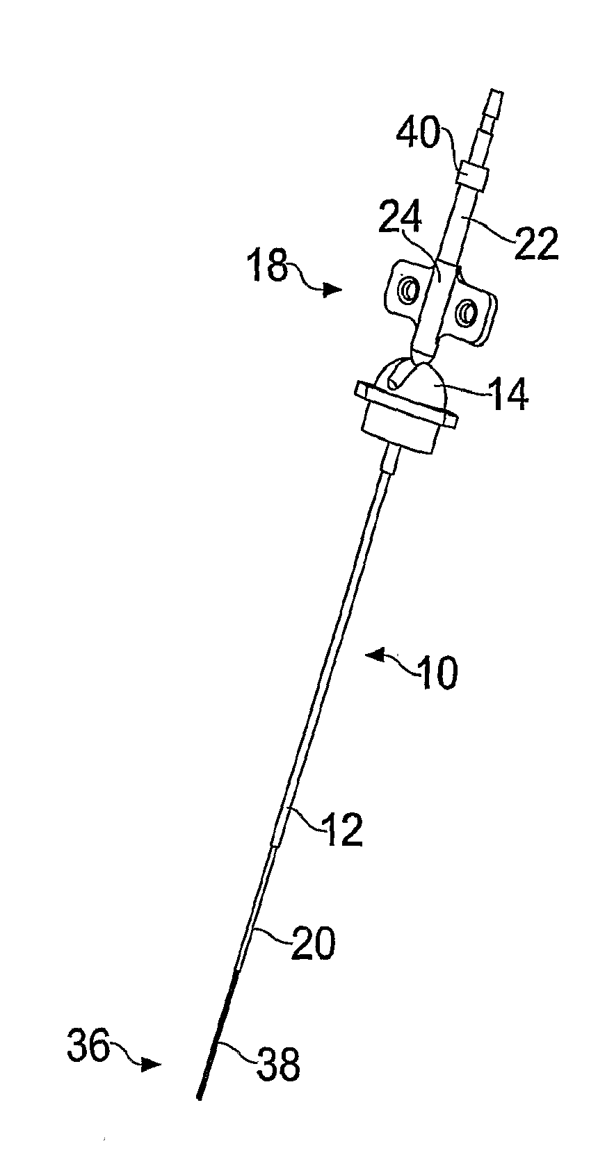
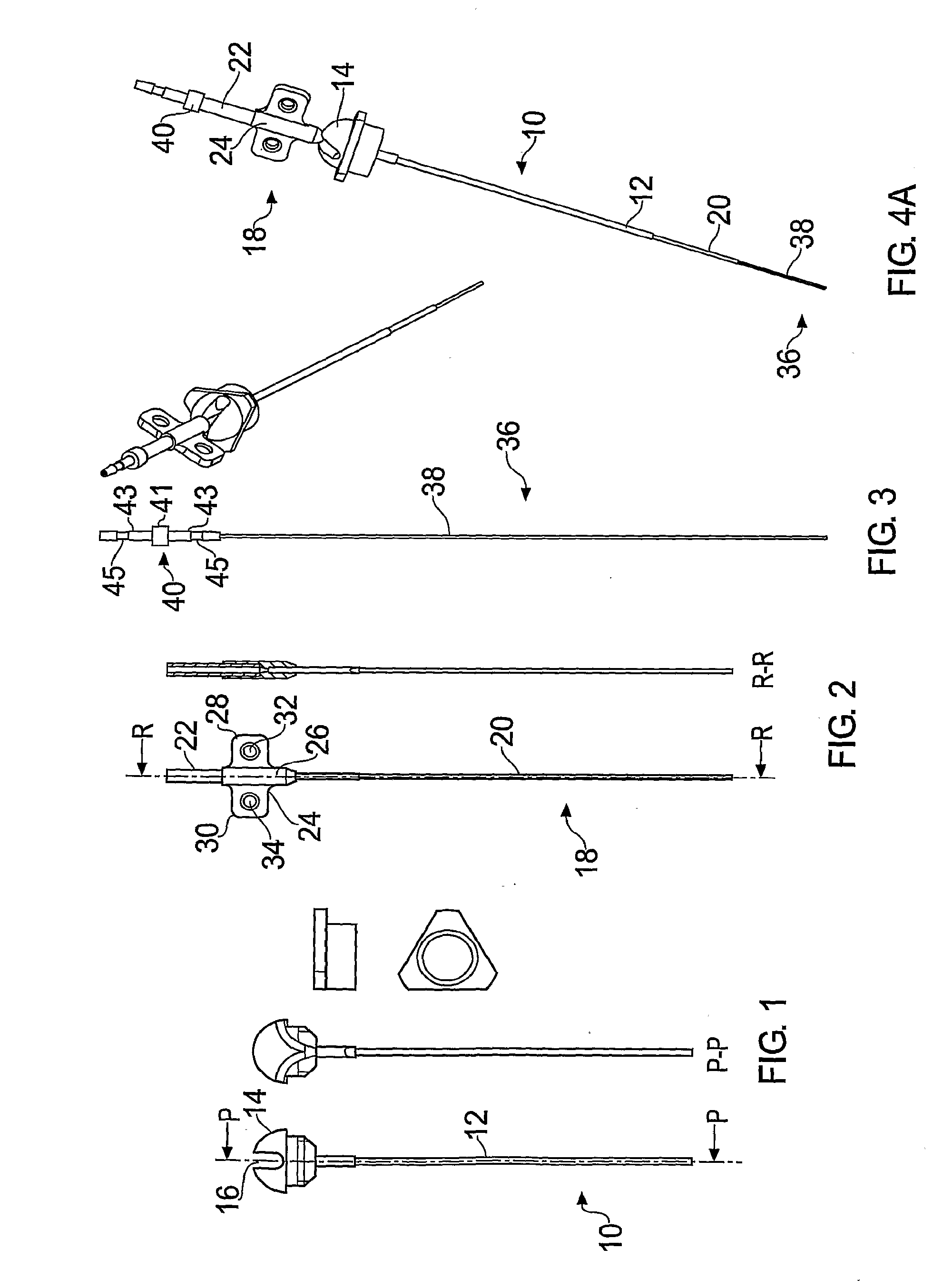
[0029]FIGS. 1-3 illustrate a guide tube, inner tube and catheter respectively according to the present invention.

[0030]The guide tube 10 is shown in FIG. 1 and comprises a length of tube 12 with a hub 14 at one end. In this example it is made from a polyurethane plastic such as carbothane 55DB20. However, it may be made from any material which is biocompatible and sufficiently rigid at room temperature to maintain its central aperture. In this example, the tube 12 has an outer diameter of 0.6 mm and an inner diameter of 0.5 mm.

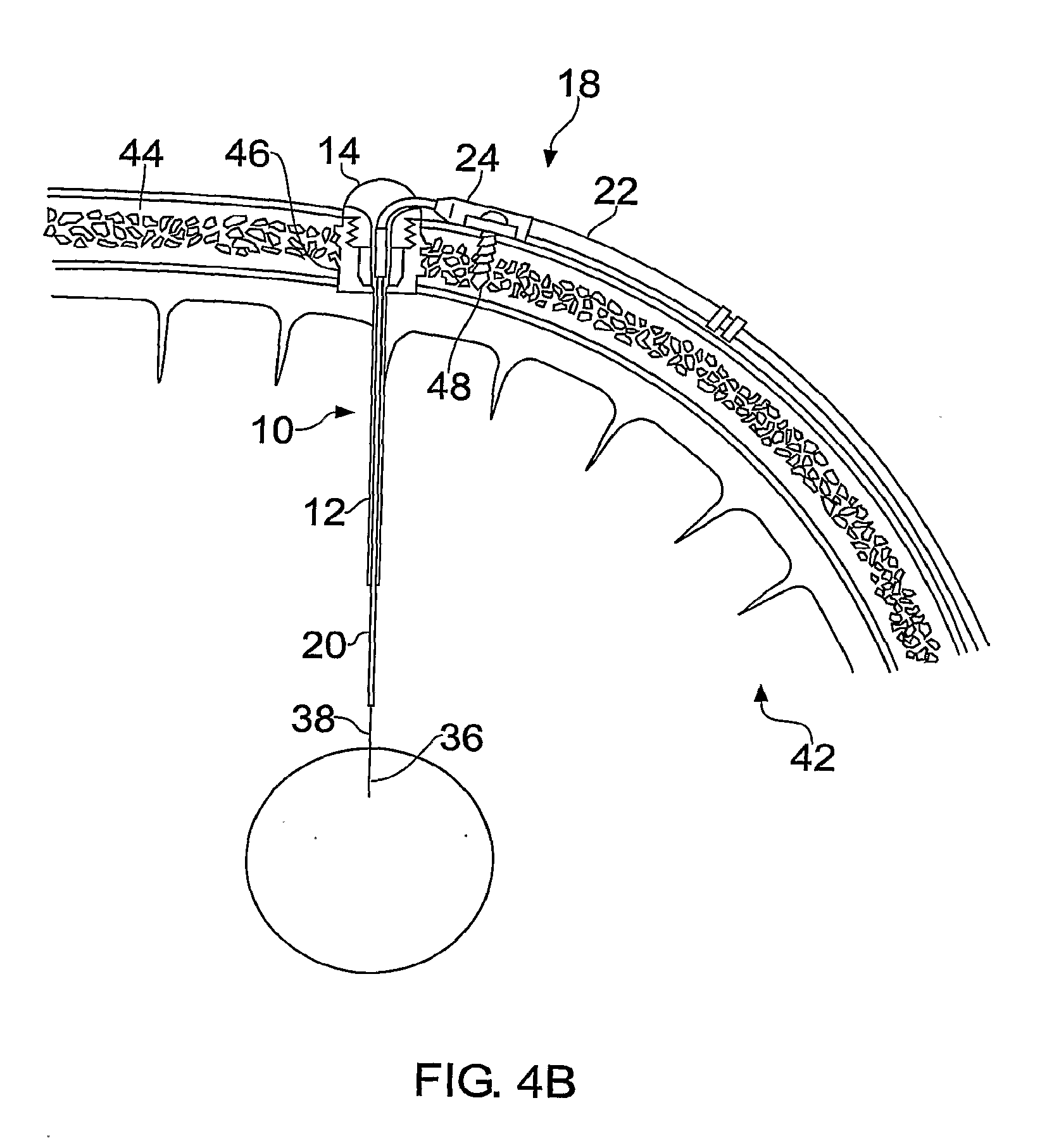
[0031]The guide tube is inserted into: the brain through an aperture (e.g. burr hole) in the skull created by the surgeon. Once the length of tubing is inserted into the brain, the hub can be attached to the patient's skull, for example by bonding into a burr hole in the skull using an acrylic cement. A wire may be used to guide the guide tube into place, as disclosed in WO03 / 07784. Before insertion, the guide tube is cut to a length short of the target. The d...


PUM

PropertyMeasurementUnit
inner diameteraaaaaaaaaa
diameteraaaaaaaaaa

Abstract

A catheter assembly for insertion into the brain. The assembly comprises a first length of tubing made of a first material. A second material surrounds the first length of tubing, the second material being more flexible than the first material and having a hardness of less than 50 Rockwell E. The second material provides damping to the first length of tubing.

Description

[0001]This is a Continuation of application Ser. No. 12 / 310,210 filed Feb. 17, 2009, which in turn is a National Phase of International Patent Application No. PCT / GB2007 / 003178 filed Aug. 20, 2007, which claims the benefit of British Patent Application No. 0616411.5 filed Aug. 18, 2006. The disclosure of the prior applications is hereby incorporated by reference herein in their entireties.FIELD OF THE INVENTION[0002]The present invention relates to apparatus for use in neurosurgery, in particular it relates to the design and use of catheters that are used to deliver therapeutic agents to the Central Nervous System.[0003]The blood-brain barrier represents a considerable hurdle to the delivery of therapeutic agents to the nervous system. The term therapeutic agent includes substances which have a therapeutic effect, such as pharmaceutic compounds, genetic materials, biologics (i.e. preparations synthesized from living organisms such as stem cells). The development of techniques to byp...

Claims


Application Information

Patent Timeline
Patent Type & Authority Applications(United States)
IPC IPC(8): A61M25/00A61L31/06A61L31/10A61M5/142A61M25/09A61M25/02A61B90/11A61L31/02A61M25/06
CPCA61M25/0045A61L31/028A61L31/06A61L31/10A61M25/0662A61M2025/0004A61M25/09A61M25/02A61B90/11A61M5/142A61M2210/0693A61M25/0097A61M2025/0042A61M25/00A61M25/005A61M25/0053A61M2025/0046A61M2025/0047A61M2025/0048A61M2025/0681A61M2025/09091A61M2210/0687
Inventor GILL, STEPHEN STREATFIELDSTRATTON, MATTHEW DAVID FREDERICKDERRICK, HUGO GEORGE
Owner RENISHAW PLC
Learn More