
Flow restrictor

a flow restrictor and restrictor technology, applied in the field of flow restrictors, can solve the problems of restrictors that cannot effectively grip the neck of medicine bottles, drug accidents, and restrictors, and achieve the effect of thinning the material

Active Publication Date: 2016-11-24
L PERRIGO
View PDF0 Cites 11 Cited by
  • Summary
  • Abstract
  • Description
  • Claims
  • Application Information

AI Technical Summary

Benefits of technology

The present invention provides improved flow restrictors for use with liquid medicine bottles that use a syringe or are squeezed to dispense medicine. The flow restrictor includes a cover with a raised ring for a tight seal and an orifice for dispensing medicine. It can be used with either a syringe or without a syringe. The orifice has a closure that default to a closed position but can be opened by either using the syringe or by squeezing the bottle. The flow restrictor is designed to provide a tight seal to the inside wall of the bottle neck and allow for manageable pressure to dose the medicine. It features a downwardly extending annular cylinder with vertical supports or ribs that engage the inside wall of the sleeve and one or more external horizontal protrusions that transfer the downward force to provide the tight seal. The flow restrictor provides improved and reliable flow control for liquid medicine bottles.

Problems solved by technology

Drug accidents may occur if a child resistant cap is not placed back on the medicine bottle and a child consumes more medicine than a prescribed or recommended dose.
However, the flow restrictor used to cover the opening of the bottle may still permit the medicine to leak because, for example, when a cap is screwed onto the bottle, a cap liner may depress the opening causing leakage.
Additionally, such a flow restrictor may not effectively grip the neck of the medicine bottle, thereby permitting the flow restrictor to be accidently pulled out of the bottle by an inserted syringe.
Additionally, some flow restrictors, positioned flush against the diameter of the mouth of the bottle, have been known to be accidently pushed into the bottle.
Further, flow restrictors used to reduce the diameter of the bottle may leak when the bottle is tipped over.
Additionally, the squeeze flow restrictors may come off when the bottle is squeezed.

Method used


Image

  • Flow restrictor
  • Flow restrictor
  • Flow restrictor

Examples


Embodiment Construction

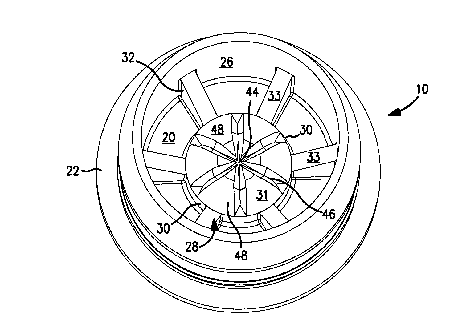
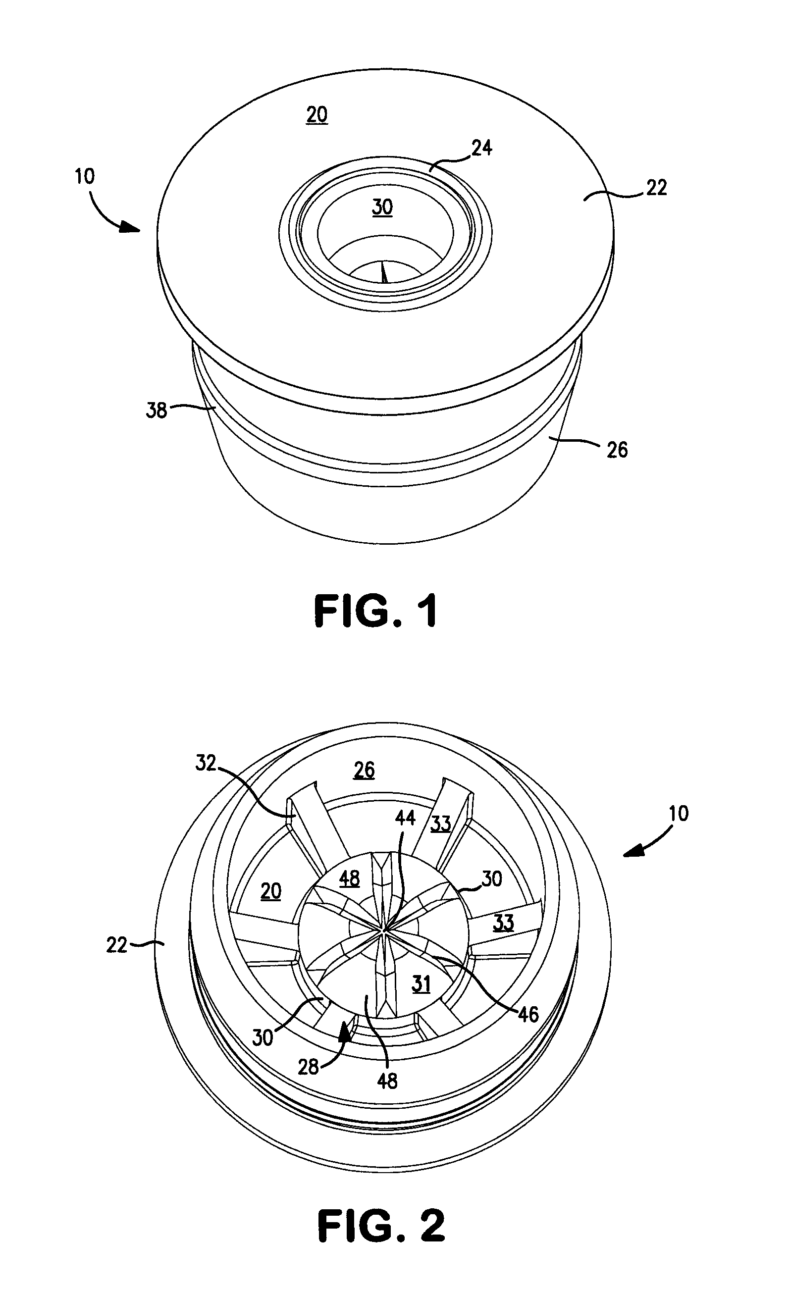
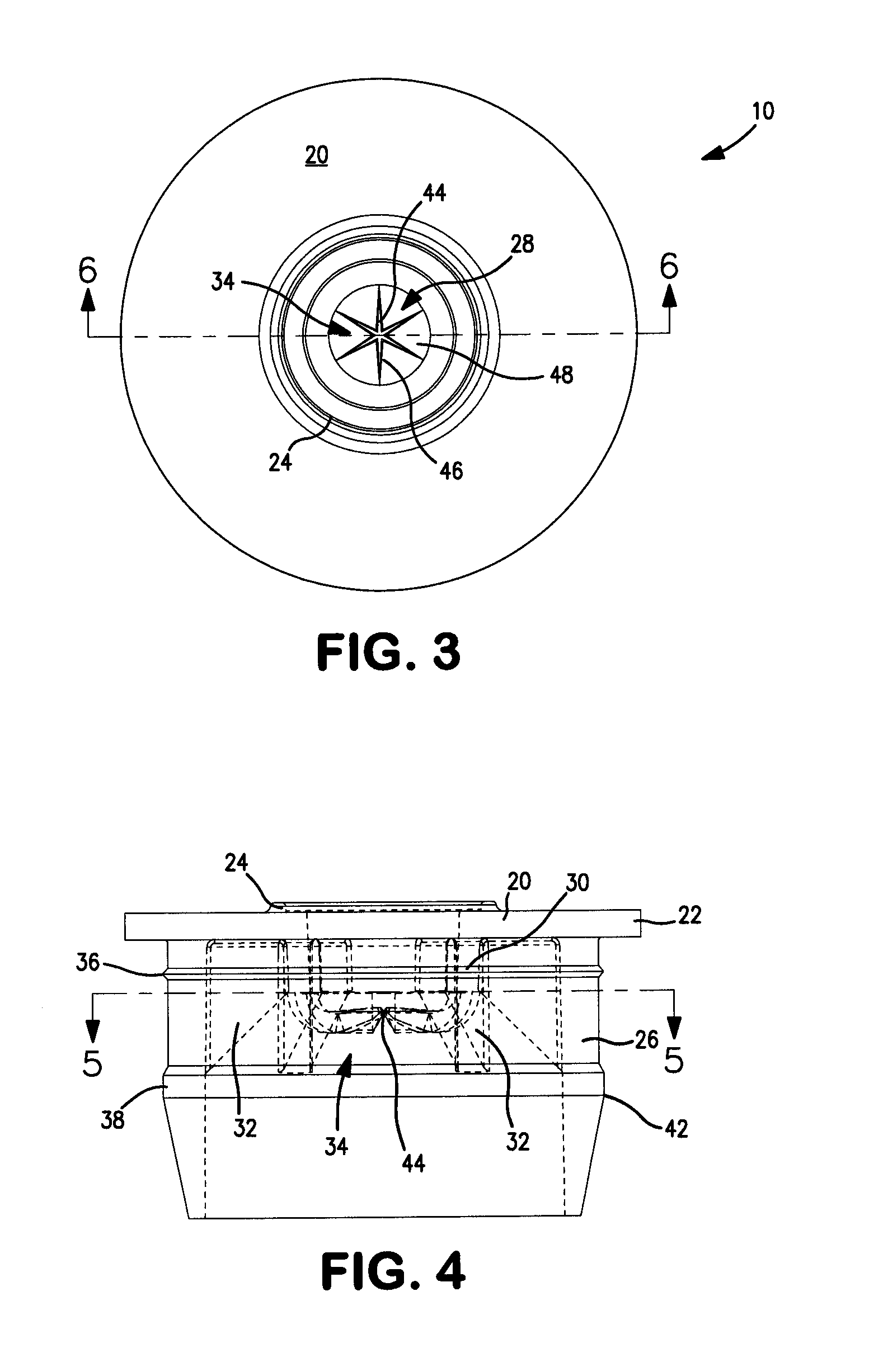
[0028]The present invention is directed to flow restrictors for use in a medicine bottle including for dispensing medicine to infants and children. The invention provides an improved flow restrictor which prevents the accidental dispensing of the liquid medicine or the leaking of the medicine from the bottle. The invention may be used with a syringe for dispensing the medicine to an infant or child or without a syringe for dispensing the medicine to a dose cup by squeezing the bottle. As seen in the drawings and hereafter, three embodiments of the flow restrictor invention are disclosed, although it is understood that other embodiments using the invention may be made by those skilled in the art without departing from the scope of the invention.

[0029]FIGS. 1-6 show a first embodiment of the invention for use with a syringe; e.g. a 20 mm flow restrictor. FIGS. 7-11 show a second embodiment of the invention for dispensing the medicine to a dose cup by squeezing the bottle; e.g. a 24 mm...


PUM


Abstract

Flow restrictors for use with a syringe or without a syringe are disclosed for dispensing a liquid medicine for an infant or child. The flow restrictors include a cover having a raised ring, a sleeve for insertion into a bottle, a self-sealing orifice for dispensing the medicine and including an annular cylinder having vertical supports or ribs which extend outward and engage the inside wall of the sleeve. The sleeve includes one or more external protrusions.

Description

FIELD OF THE INVENTION[0001]The present invention relates to flow restrictors. More particularly, the invention relates to flow restrictors for use in infant and children's liquid medicine bottles.BACKGROUND OF THE INVENTION[0002]The flow restrictor inventions are directed to use in infant and children's liquid medicine bottles, including for ibuprofen and acetaminophen. Drug accidents may occur if a child resistant cap is not placed back on the medicine bottle and a child consumes more medicine than a prescribed or recommended dose. To prevent such accidents, flow restrictors have been added to the top of the bottle. Such flow restrictors may be used with a syringe inserted into the flow restrictor for removal of the liquid medicine from the bottle and to dispense the medicine to the infant or child; or a flow restrictor wherein when the medicine bottle is squeezed and the flow restrictor has an aperture which opens to dispense the liquid medicine to a dose cup.[0003]For example, t...

Claims


Application Information

Patent Timeline
Patent Type & Authority Applications(United States)
IPC IPC(8): A61J1/22A61J1/14
CPCA61J1/1468A61J1/22A61J1/2096B65D47/2031A61J1/1412
Inventor OBERLIN, PAUL D.REITER, MICHAEL S.
Owner L PERRIGO
Learn More