
Bicycle bag

a bicycle and shoulder strap technology, applied in the field of bicycle bags, can solve the problems of easy damage to the connection portions between the support strap and the bag body, large volume of the conventional bicycle bag, and easy damage to the bag body, and achieve the effect of thin material

Inactive Publication Date: 2010-12-23
DAHON & HON IND LABS LTD
View PDF9 Cites 23 Cited by
  • Summary
  • Abstract
  • Description
  • Claims
  • Application Information

AI Technical Summary

Benefits of technology

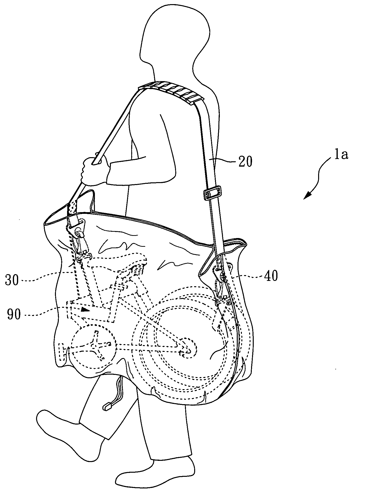
[0012]The major characteristic of the present invention is that the main support strap, the first connection device, and the second connection device are directly or indirectly connected with each other. The first connection device and the second connection device are used to fasten a bicycle. Therefore, when the first connection device and the second connection device support the weight of the bicycle, the main support strap is capable of bearing such a force. As a result, the covering body of the present invention barely needs to or completely needs not to bear the weight of the bicycle, such that the covering body of the present invention can be a very thin sheet. Compared to a conventional bicycle bag, which has a relatively thicker bag body, the bicycle bag of the present invention is much lighter.
[0013]Further, because the covering body of the present invention barely needs to or completely needs not to bear the weight of the bicycle, connection portions between the main support strap and the covering body are not easily damaged, such that the bicycle bag of the present invention is more durable and has a longer life.

Problems solved by technology

However, the bag body 81b still needs to share a significant weight of the bicycle.
Accordingly, the volume of the conventional bicycle bag is still quite large, even when the bag is empty.
That is, the connection portions between the support strap and the bag body are easily damaged, and the fabric of the bag body has to be very durable; otherwise, the bag body will easily damaged.
In U.S. Pat. No. 6,202,722 (Wheelchair carrier), the wheelchair carrier applies the same approach to connecting the support strap with the bag body as the '988 patent does, thereby resulting in the same problem.

Method used


Image

  • Bicycle bag
  • Bicycle bag
  • Bicycle bag

Examples


first embodiment

[0029]Please refer to FIG. 3 and FIGS. 3C˜3F regarding the present invention.

[0030]A bicycle bag 1 a of the present invention comprises a covering body 10, a main support strap 20, a first connection device 30, and a second connection device 40.

[0031]The covering body 10 mainly comprises a thin sheet 18. The thin sheet 18 is preferably made of soft materials, such as plastic cloth (like PVC, PU or nylon), synthetic leather, or the like. The thickness of the thin sheet 18 is preferably less than 0.2 mm. In this embodiment, the thin sheet 18 is rectangular in shape and can be rolled to form a tube, such that the covering body 10 has an upper opening 11 and a lower opening 12, and the inside of the tube formed by the thin sheet 18 thereby creates a storage space 13 for placing a bicycle 90 (as shown in FIG. 3).

[0032]The covering body 10 further comprises an upper connection member 15, such as a zipper 15a, a hook and loop (also known as Velcro), ect. The zipper 15a is attached to the t...


PUM


Abstract

A bicycle bag which comprises a covering body, a main support strap, a first connection device and a second connection device is disclosed. The major characteristic of the present invention is that the main support strap, the first connection device, and the second connection device are directly or indirectly connected with each other. By means of associating with connection members, the first connection device and the second connection device can be fastened to a bicycle. Therefore, when the first connection device and the second connection device receive a force from the weight of the bicycle, the main support strap is capable of bearing such a force.

Description

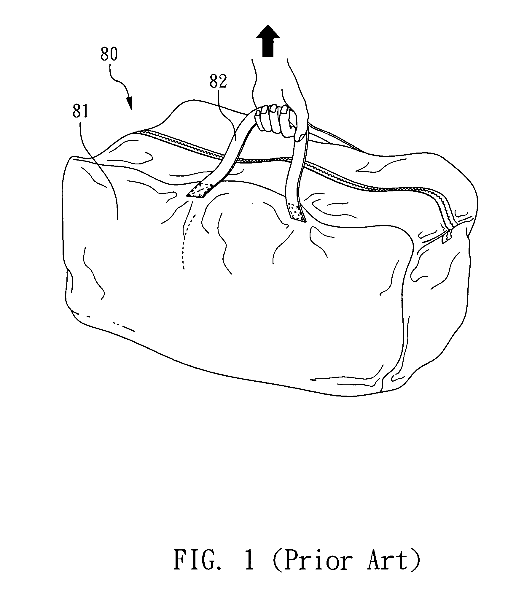
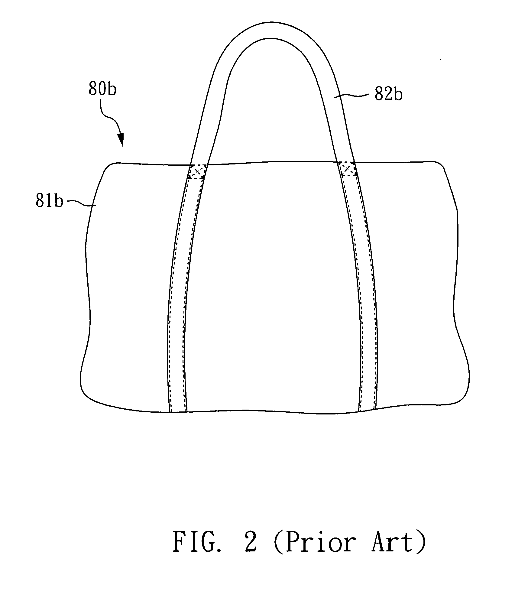
BACKGROUND OF THE INVENTION[0001]1. Field of the Invention[0002]The present invention relates to a shoulder bag or a handbag; more particularly, the present invention relates to a bag used for containing a bicycle.[0003]2. Description of the Related Art[0004]Please refer to FIG. 1, which illustrates a schematic drawing of a known bicycle bag 80 according to a prior art. As shown in FIG. 1, support straps 82 are connected with a bag body 81. Because the bag body 81 has to bear the total weight of the contents of the bicycle bag 80, the fabric and structure of the bag body 81 have to be thick and sufficiently durable. Further, because the connection portions 83 between the support straps 82 and the bag body 81 are used for carrying the total weight of the bicycle placed within the bag 80, the connection portions 83 are always the most easily damaged parts of the bicycle bag 80.[0005]Another prior art, as shown in FIG. 2, a support straps 82b is attached to a bag body 81b with a surrou...

Claims


Application Information

Patent Timeline
Patent Type & Authority Applications(United States)
IPC IPC(8): A45F3/04A45F5/00
CPCA45C3/00A45C3/001A45F3/04A45C13/1046A45C13/30A45C13/02B62J19/00B62J50/10
Inventor UIMONEN, JOAKIM
Owner DAHON & HON IND LABS LTD
Learn More