
Structural member stabilizing system

Inactive Publication Date: 2007-01-16
ROTH STEVEN A
View PDF7 Cites 22 Cited by
  • Summary
  • Abstract
  • Description
  • Claims
  • Application Information

AI Technical Summary

Benefits of technology

[0004]The present invention provides an arrangement whereby a bracket of integral construction will not rotate relative to the channel member or other structural member with which it is associated. The bracket serves to transfer load caused by the associated cables to the channel member or other structural member to which the bracket is connected. This enables the bracket to be constructed of thinner gauge material than would otherwise be the case. The arrangement of the present invention allows the structural member and the bracket to remain in fixed position even if the cables are not perfectly aligned with apertures of the bracket.
[0005]The bracket of the present invention is of integral construction and is for connecting a structural member to a structural element and also for stabilizing the structural member against movement when connected thereto.
[0009]The bracket also includes a bearing element connected to the bracket base and including a bearing element surface for bearing against the structural member at a second location on the structural member. The bearing element surface is angularly disposed relative to the bracket base surface and transfers force from the bracket to the structural member when bearing against the structural member to prevent relative rotational movement between the bracket and the structural member.

Problems solved by technology

This can cause loosening of the bracket and cause undesirable stresses to be exerted on the bracket and the object.
Any deviation of non-perfect alignment between the bracket apparatus and the cables can result in this rotational or twisting action.

Method used


Image

  • Structural member stabilizing system
  • Structural member stabilizing system
  • Structural member stabilizing system

Examples


Embodiment Construction

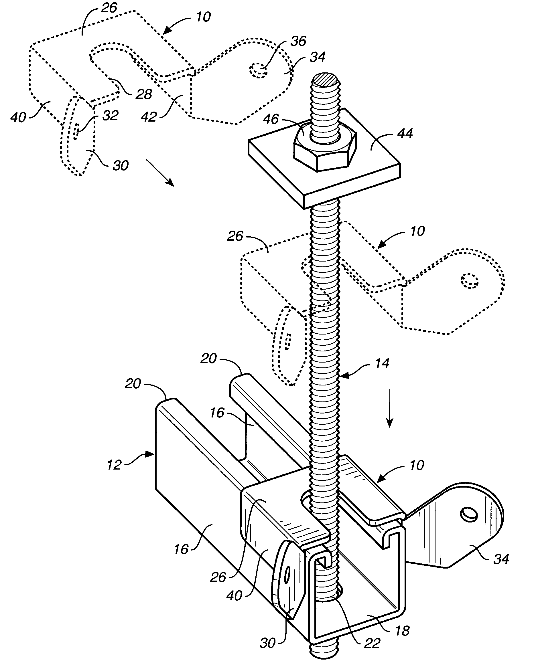
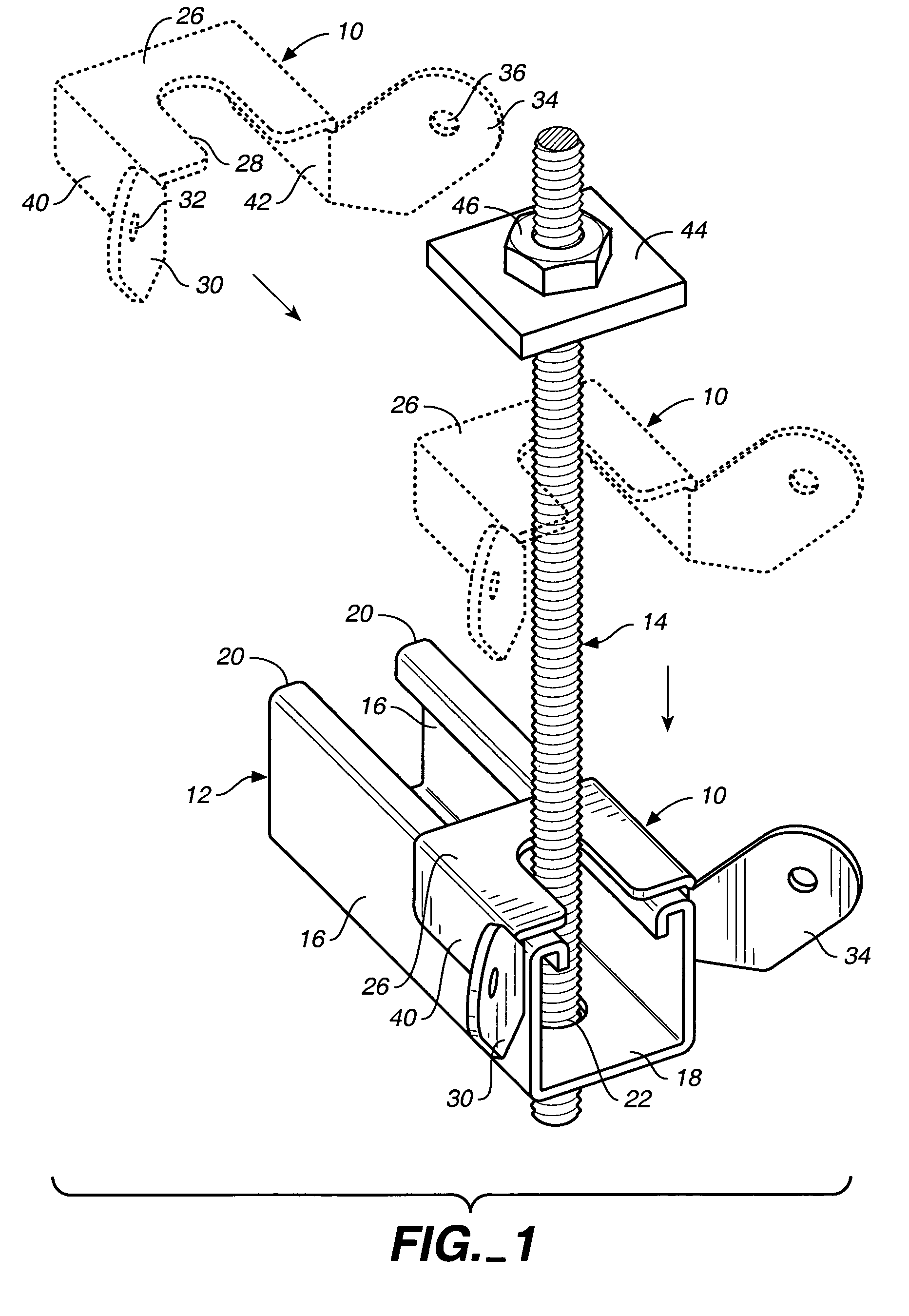
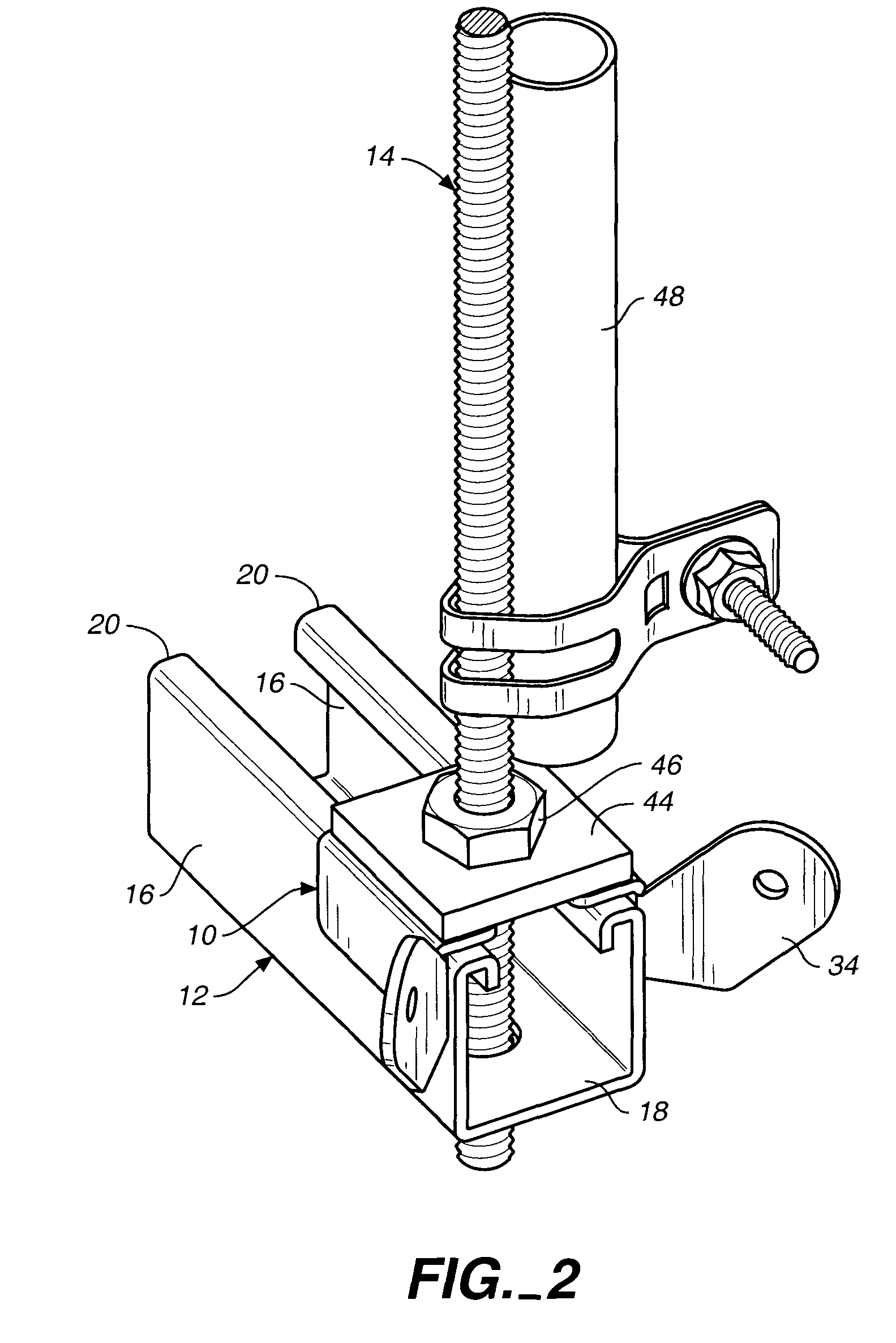
[0019]Referring now to FIGS. 1 and 2, a bracket 10 constructed in accordance with the teachings of the present invention is illustrated. The bracket is of integral construction and is utilized to connect a structural member to a structural element and for stabilizing the structural member against movement when connected thereto.

[0020]In this instance, the structural member is a conventional open-ended channel member 12 and the structural element is a conventional threaded hanger rod 14. It will be understood that the hanger rod 14 depends downwardly from a ceiling or other building structure (not shown).

[0021]The open-ended channel member 12 has two side channel member walls 16, a bottom channel member wall 18 and inturned lips 20 at the tops of the side channel member walls defining an elongated opening communicating with the interior of the channel member. An aperture 22 in the bottom channel member wall receives the hanger rod, as shown.

[0022]The bracket 10 includes a bracket bas...


PUM


Abstract

A bracket connects a structural member to a structural element to stabilize the structural member against movement. The bracket includes connector portions for connecting the bracket to tensioned stabilizing cables or other structural stabilizing elements and one or more bearing elements which bear against the structural member to prevent relative rotational movement between the bracket and the structural member.

Description

TECHNICAL FIELD[0001]This invention relates to a bracket of integral construction for connecting a structural member to a structural element and for stabilizing the structural member against movement when connected thereto. The invention has particular application to connecting a channel member to a hanger rod.BACKGROUND OF THE INVENTION[0002]U.S. Pat. No. 6,026,545, issued Feb. 22, 2000, discloses a one-piece restraint bracket used with cables to brace a supported object against movement. The bracket is generally L-shaped to define a flattened, apertured central portion with two wing portions generally at right angles to each other, apertured at their free ends and joined to the flattened central portion. Each wing is elevated or upwardly bent from the plane of the central portion. Cables are attached to the wing portions and are tensioned to brace the bracket against movement when there is seismic activity or the like.[0003]With the device of U.S. Pat. No. 6,026,545 unequal forces...

Claims


Application Information

Patent Timeline
IPC IPC(8): E04H12/34
CPCE04B9/183F16L3/24E04B9/20F16L3/245F16L3/243
Inventor ROTH, STEVEN A.
Owner ROTH STEVEN A
Learn More