Optical touch device and sensing method thereof

a technology of optical touch and sensing method, which is applied in the direction of instruments, computing, electric digital data processing, etc., can solve the problems of inconvenient application to large-size devices, capacitive or resistive touch screens, and limited manufacturing costs, so as to simplify the flow of determining touch points and reduce reliability

Active Publication Date: 2016-11-17
WISTRON CORP
View PDF3 Cites 6 Cited by
  • Summary
  • Abstract
  • Description
  • Claims
  • Application Information

AI Technical Summary

Benefits of technology

The invention is an optical touch device that uses multiple sets of optical sensors to detect touch. The device excludes data from areas with lower reliability to simplify the process of determining touch points. By excluding data from sets of sensors that are in the "no-touch" area, the device can make a more accurate determination without taking into account data that may not be reliable. This results in a higher touch point detection accuracy.

Problems solved by technology

However, limited by manufacturing cost and a touch effect, capacitive or resistive touch screens are only adapted to small and middle-size devices such as mobile phones, tablet personal computers (PCs), notebooks, and all-in-one (AIO) computers, and are not suitable for being applied to large-size devices due to reasons of cost, reliability, etc.
However, when the number of the touch objects is greater than two, it is complicated for the processing unit to identify and calculate positions of touch points, and an error or an interference is liable to be occurred, for example, the so-called “ghost points problem”.
However, when the touch devices are increased, the method for determining the touch points becomes more complicated, and a required computation amount is also increased.
On the other hand, the touch device composed of more than two optical sensing modules also has areas with less sensing accuracy, for example, when the position of the touch object is very close to a connection line between the two optical sensing modules, the intersection sensed by the touch device is inaccurate.
Alternatively, limited by an image resolution of the optical sensing modules, the touch device cannot accurately identify or determine the real touch points and ghost points located beyond a certain large distance or within a certain angle range, which may lead to a wrong judgement for the real touch points.

Method used


Image

  • Optical touch device and sensing method thereof
  • Optical touch device and sensing method thereof
  • Optical touch device and sensing method thereof

Examples


Embodiment Construction

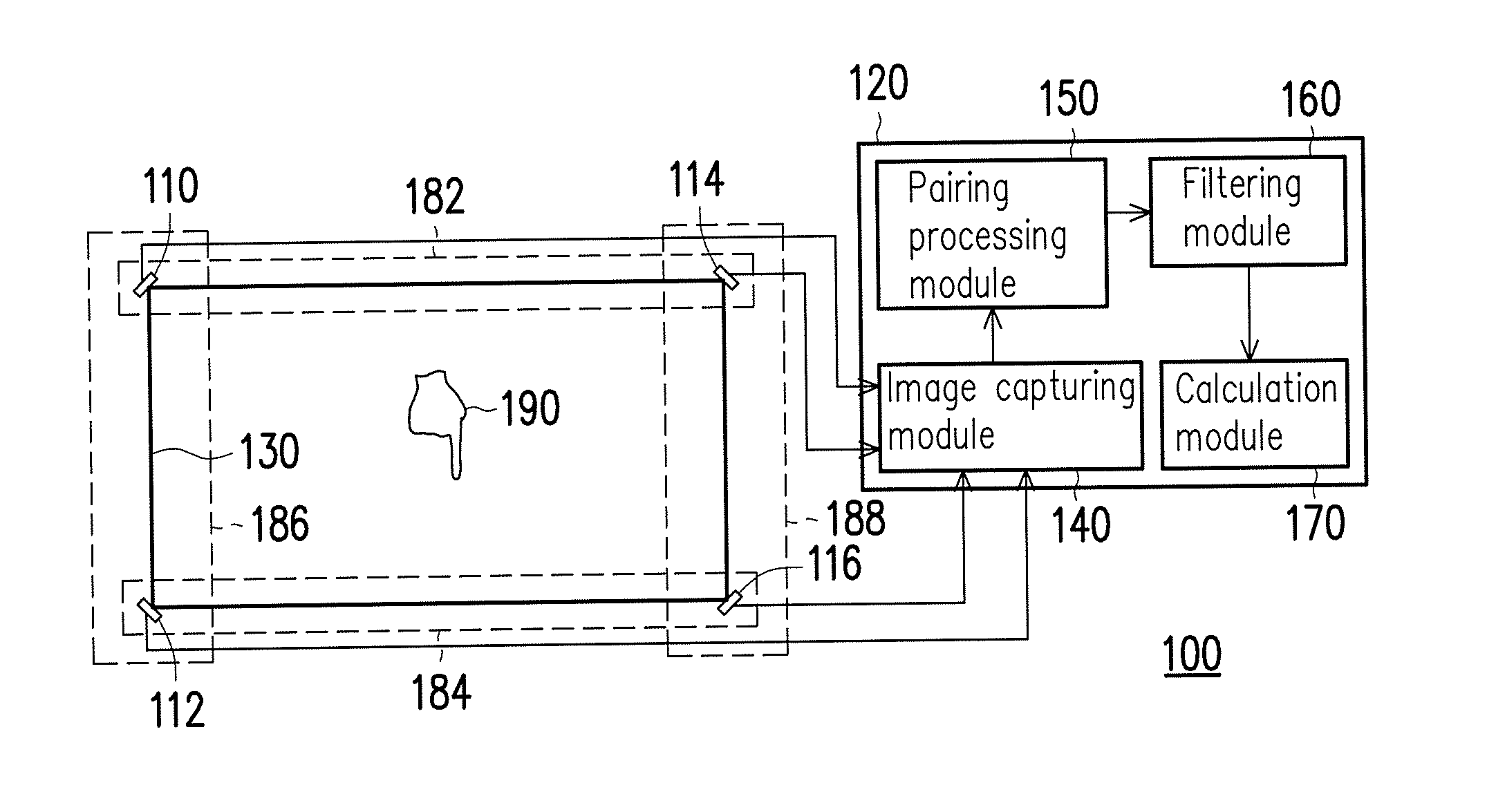
[0019]In order to accurately detect a touch object by using an optical touch technique, an optical touch device of the invention is configured with a plurality sets of optical sensing modules, and a touch-excluded area with lower reliability is set according to a position of each set of the optical sensing modules. Since touch areas of the optical sensing modules are overlapped to each other, when a part of coordinates data generated by one set of the optical sensing module is in the touch-excluded area with lower reliability, the part of coordinates data in the touch-excluded area with lower reliability is excluded, and the coordinate data with higher reliability is retained. In this way, the optical touch device of the invention can exclude the coordinates data with lower reliability to decrease the number of coordinates data obtained when each touch point is sensed, so as to simplify a determination process of the touch points and increase determination accuracy. Embodiments are ...


PUM


Abstract

An optical touch device and a sensing method thereof are provided. The optical touch device includes a plurality of optical sensors and a processing unit. The optical sensors are arranged around a touch plane and are spaced from each other. The two adjacent optical sensors located at one side of the touch plane are defined as one set of an optical sensing module, such that the optical sensors are paired to form multiple sets of the optical sensing modules. The processing unit generates a plurality of touch coordinates data corresponding to the plurality sets of the optical sensing modules according to the optical touch data, and determines whether the touch coordinates data corresponding to each set of the optical sensing modules is in at least one touch-excluded area corresponding to each set of the optical sensing modules, and respectively excludes the touch coordinates data in the touch-excluded area.

Description

CROSS-REFERENCE TO RELATED APPLICATION[0001]This application claims the priority benefit of Taiwan application serial no. 104115049, filed on May 12, 2015. The entirety of the above-mentioned patent application is hereby incorporated by reference herein and made a part of this specification.BACKGROUND OF THE INVENTION[0002]1. Field of the Invention[0003]The invention relates to a touch sensing technique, and particularly relates to an optical touch sensing device having a plurality of optical sensing modules and a sensing method thereof.[0004]2. Description of Related Art[0005]Electronic devices or display screens having a touch function have gradually become a development trend of today's technology. However, limited by manufacturing cost and a touch effect, capacitive or resistive touch screens are only adapted to small and middle-size devices such as mobile phones, tablet personal computers (PCs), notebooks, and all-in-one (AIO) computers, and are not suitable for being applied t...

Claims


Application Information

Patent Timeline
IPC IPC(8): G06F3/042
CPCG06F3/0425G06F3/0421G06F3/04166G06F3/0428
Inventor WU, BO-YICHEN, YU-YENLU, KUO-HSIENKAN, WEI-KUOHUANG, KUO-TINGCHO, CHING-ANCHIU, CHIH-HAOYU, CHAN-HSUANSYU, YOU-JYUN
Owner WISTRON CORP
Why Eureka
Try Eureka