
EV Muti-Mode Thermal Control System

a technology of thermal control system and electric motor, which is applied in the direction of battery/fuel cell control arrangement, electric devices, battery/cell propulsion, etc., can solve the problems of increased cost and weight, increased complexity of the drive train of a hybrid vehicle, and emission of harmful pollution, etc., to achieve efficient thermal control of the drive train components.

Active Publication Date: 2016-11-03
ATIEVA USA INC
View PDF0 Cites 48 Cited by
  • Summary
  • Abstract
  • Description
  • Claims
  • Application Information

AI Technical Summary

Benefits of technology

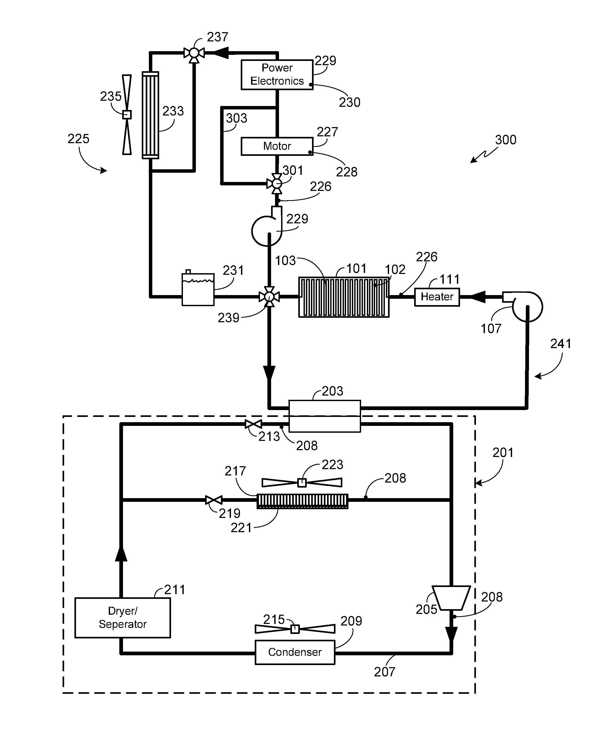
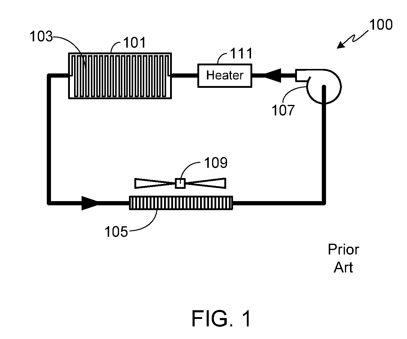
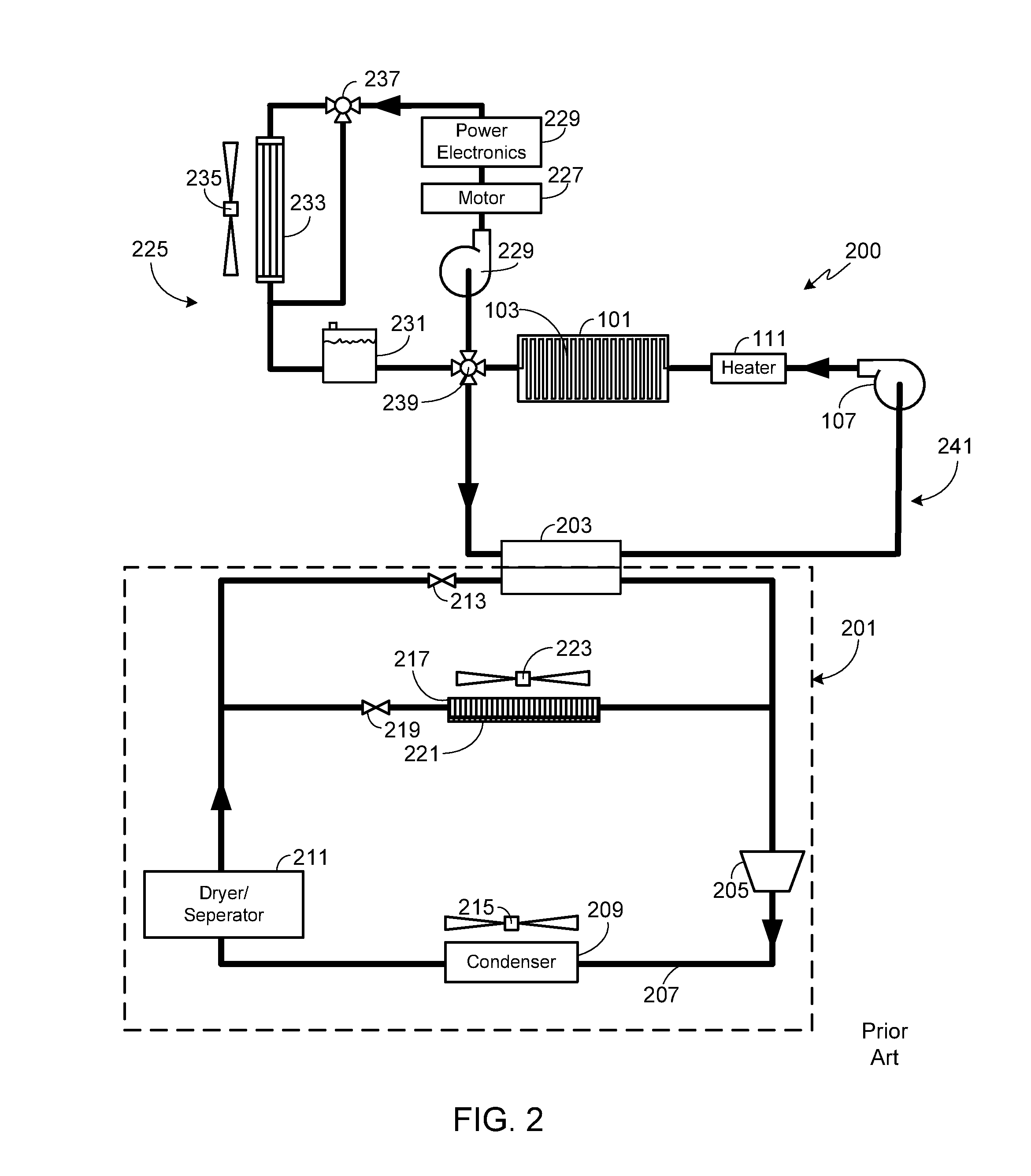
The present invention provides a thermal management system for vehicles that efficiently controls the temperature of the drive train components. The system includes a drive train thermal control loop with a multi-mode valve assembly and a first and second valve assembly. The system can decouple the drive train thermal control loop from the primary drive train component and allow the heat transfer fluid to by-pass the primary component in series with the secondary component in the first operational mode, or to only be thermally coupled to the primary component in the second operational mode. The system can also include a coolant reservoir, a radiator, a diverter valve, and a supplemental electric heater. Additionally, the system can include a refrigerant-based thermal control loop with a compressor, condenser / evaporator, and refrigerant-air heat exchanger.

Problems solved by technology

While hybrid vehicles provide improved gas mileage and lower vehicle emissions than a conventional ICE-based vehicle, due to their inclusion of an internal combustion engine they still emit harmful pollution, albeit at a reduced level compared to a conventional vehicle.
Additionally, due to the inclusion of both an internal combustion engine and an electric motor(s) with its accompanying battery pack, the drive train of a hybrid vehicle is typically much more complex than that of either a conventional ICE-based vehicle or an all-electric vehicle, resulting in increased cost and weight.

Method used


Image

  • EV Muti-Mode Thermal Control System
  • EV Muti-Mode Thermal Control System
  • EV Muti-Mode Thermal Control System

Examples


Embodiment Construction

[0034]As used herein, the singular forms “a”, “an” and “the” are intended to include the plural forms as well, unless the context clearly indicates otherwise. The terms “comprises”, “comprising”, “includes”, and / or “including”, as used herein, specify the presence of stated features, integers, steps, operations, elements, and / or components, but do not preclude the presence or addition of one or more other features, integers, steps, operations, elements, components, and / or groups thereof. As used herein, the term “and / or” and the symbol “ / ” are meant to include any and all combinations of one or more of the associated listed items. Additionally, while the terms first, second, etc. may be used herein to describe various steps, calculations or components, these steps, calculations or components should not be limited by these terms, rather these terms are only used to distinguish one step, calculation or component from another. For example, a first calculation could be termed a second c...


PUM


Abstract

A thermal management system that utilizes a multi-mode valve assembly within the drive train control loop to provide efficient thermal control of the drive train components is provided. The multi-mode valve assembly allows the mode of thermal coupling between the thermal control loop and the various drive train components (e.g., vehicle propulsion motor, gearbox assembly, power electronics subsystem, etc.) to be varied in accordance with present conditions.

Description

CROSS-REFERENCE TO RELATED APPLICATION[0001]This application is a continuation-in-part of U.S. patent application Ser. No. 14 / 698,394, filed 28 Apr. 2015, the disclosure of which is incorporated herein by reference for any and all purposes.FIELD OF THE INVENTION[0002]The present invention relates generally to the electric motor assembly of an electric vehicle and, more particularly, to a cooling system that can be used to effectively and efficiently cool the motor assembly and related drive train components of an electric vehicle.BACKGROUND OF THE INVENTION[0003]In response to the demands of consumers who are driven both by ever-escalating fuel prices and the dire consequences of global warming, the automobile industry is slowly starting to embrace the need for ultra-low emission, high efficiency cars. While some within the industry are attempting to achieve these goals by engineering more efficient internal combustion engines, others are incorporating hybrid or all-electric drive t...

Claims


Application Information

Patent Timeline
Patent Type & Authority Applications(United States)
IPC IPC(8): B60H1/00B60H1/32B60L11/18B60H1/22
CPCB60H1/00278B60H1/00271B60H1/2215B60L2240/36B60L11/187B60H2001/00307B60H1/323B60H1/2221B60H1/3211B60L1/003B60L1/06B60L3/003B60L3/0061B60L2240/12B60L2240/34B60L2240/425B60L2240/525B60L2240/545B60L2240/662B60L50/51B60L58/26B60L58/27B60H1/32281Y02T10/70Y02T10/72Y02T90/16
Inventor RAWLINSON, PETER DORE
Owner ATIEVA USA INC
Learn More