
Computer vision collision avoidance in drilling operations

a collision avoidance and computer vision technology, applied in the direction of image generation, instruments, borehole/well accessories, etc., can solve the problems of unfulfilled automation, tool subsystems that pose new challenges, and avoidance of automated tools presenting an unnecessary distraction to the drill hand, so as to improve the conventional collision avoidance system

Active Publication Date: 2016-10-06
TRANSOCEAN SEDCO FOREX VENTURES LTD
View PDF11 Cites 24 Cited by
  • Summary
  • Abstract
  • Description
  • Claims
  • Application Information

AI Technical Summary

Benefits of technology

The patent describes a system that uses visual tracking to avoid collisions between drill floor personnel and tools. This system ensures that the tools operate safely without hitting anyone on the floor. It also improves upon existing collision avoidance systems by adding a new degree of freedom to track and control the tools based on visual information from the drill floor.

Problems solved by technology

The overwhelming majority of drilling operations are not fully automated, therefore some tasks are still performed by humans working alongside heavy drilling machinery.
The automated tool subsystems pose new challenges for maintaining a safe operating environment where man and machine must share the same workspace.
The avoidance of an automated tool presents an unnecessary distraction to a drill hand in an already hazardous environment.

Method used


Image

  • Computer vision collision avoidance in drilling operations
  • Computer vision collision avoidance in drilling operations
  • Computer vision collision avoidance in drilling operations

Examples


Embodiment Construction

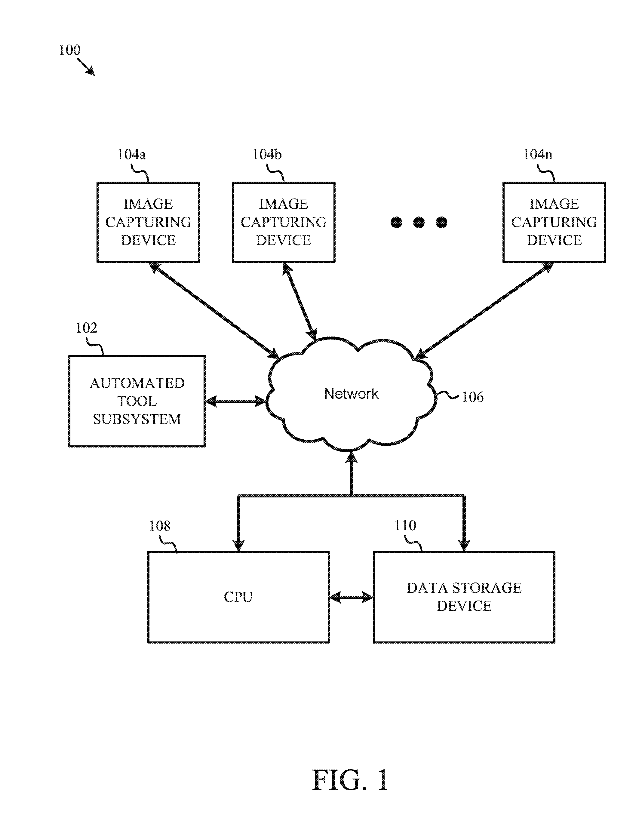
[0016]FIG. 1 is a schematic block diagram illustrating a computer vision collision avoidance system according to one embodiment of the disclosure. A computer vision collision avoidance system 100 may include an automated tool subsystem 102, one or more image capturing devices 104a-104n, a network 106, a central processing unit (CPU) 108, and a data storage device 110. In some embodiments, the automated tool subsystem 102 may implement collision avoidance. For example, the automated tool subsystem 102 may include one or more processors to control one or more tools on a drill floor in order to prevent the one or more tools on the drill floor from colliding with one another.

[0017]According to an embodiment, the one or more image capturing devices 104a-104n may be configured to capture one or more images of a working space. In some embodiments, an image capturing device, such as any one or more of image capturing devices 104a-104n, may be a still image capturing device, such as a camera...


PUM


Abstract

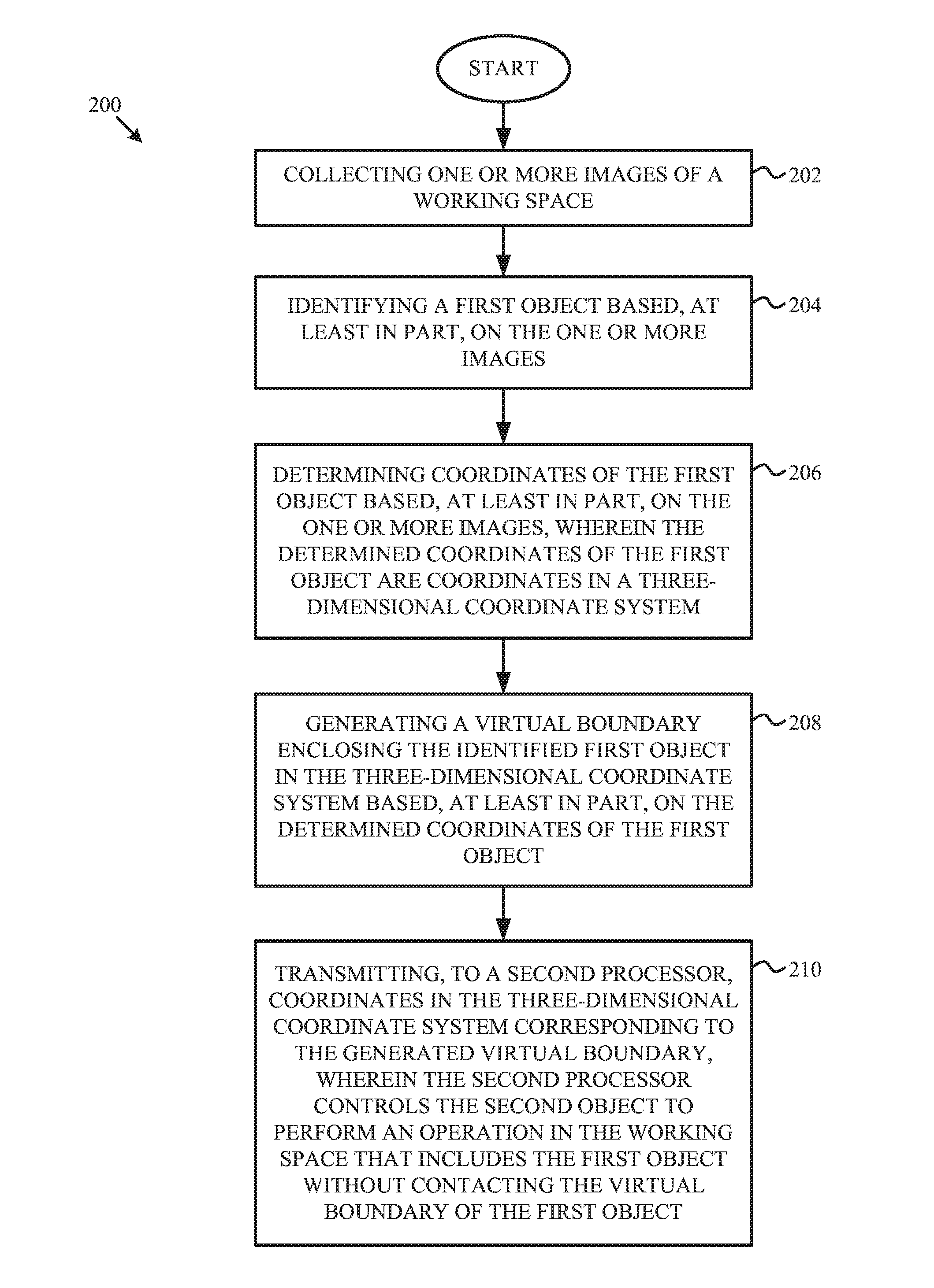
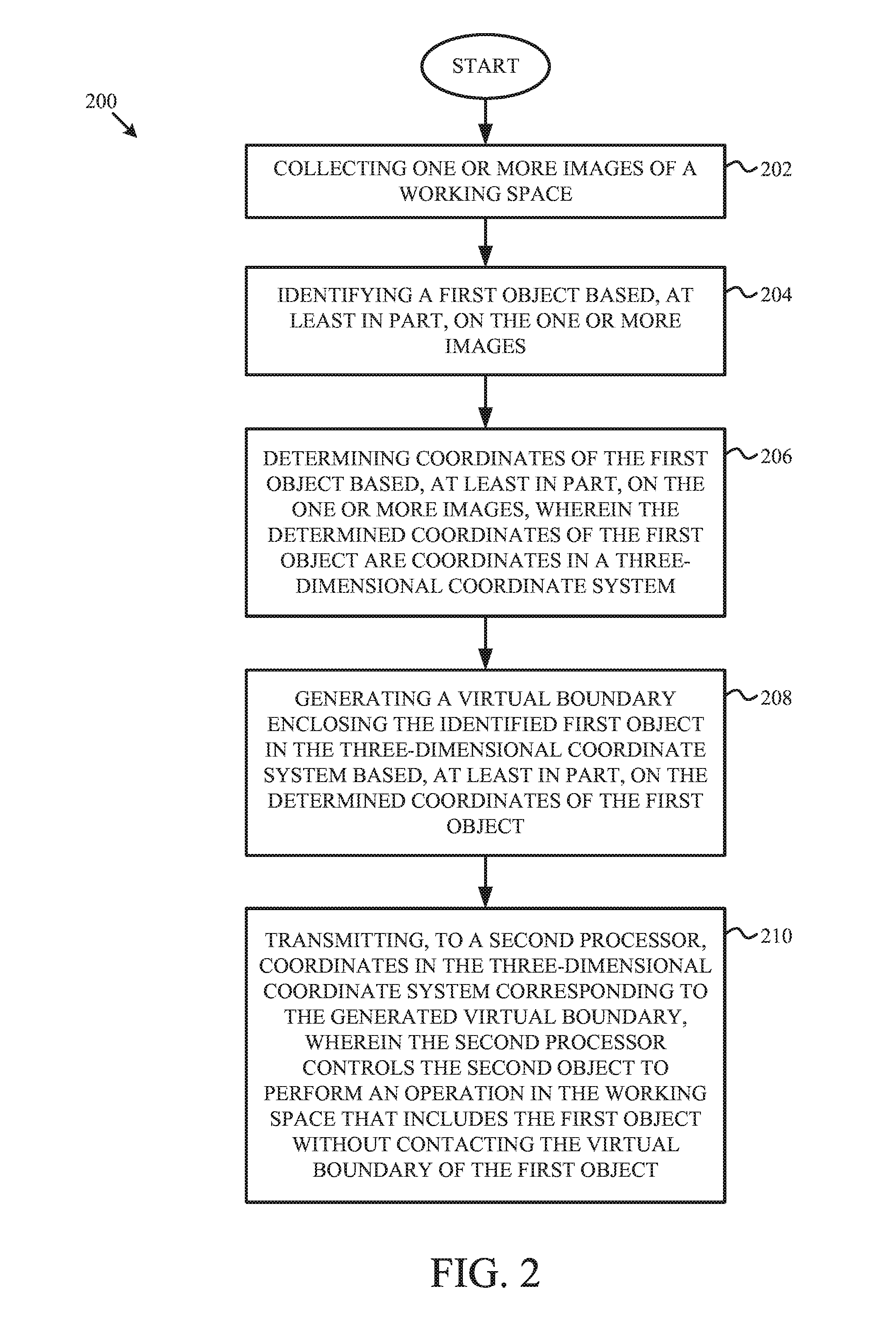
A system and method for automatically preventing a collision between objects is described. One or more images of a working space may be collected, and a first object may be identified based on the one or more images. Three-dimensional coordinates of the first object may be determined, and a virtual boundary enclosing the identified first object in a three-dimensional coordinate system may be generated based on the three-dimensional coordinates of the first object, wherein the virtual boundary specifies a volume in the working space that a second object in the working space should not occupy. The coordinates in the three-dimensional coordinate system corresponding to the generated virtual boundary may be transmitted to a second processor, and the second processor may control the second object to perform an operation in the working space that includes the first object without contacting the virtual boundary of the first object.

Description

CROSS REFERENCE TO RELATED APPLICATION[0001]This application is a continuation of U.S. patent application Ser. No. 14 / 284,196 to Kozicz et al. entitled “Computer Vision Collision Avoidance in Drilling Operations” filed on May 21, 2014, which claims the benefit of priority of provisional Patent Application No. 61 / 825,898, filed on May 21, 2013, the entire contents of both of which are incorporated herein by reference.TECHNICAL FIELD[0002]The instant disclosure relates to control systems in drilling operations. More specifically, this disclosure relates to a computer vision collision avoidance system in drilling operations.BACKGROUND[0003]Oil and gas drilling operations have evolved over the years to include multiple automated tool subsystems. Automated tool subsystems aid in executing repetitive tasks on the drill floor including drilling, tripping, casing, and cementing. Tool automation optimizes the rate of penetration, makes hole quality more consistent, reduces operation time, im...

Claims


Application Information

Patent Timeline
Patent Type & Authority Applications(United States)
IPC IPC(8): G06K9/00G06T7/00E21B41/00G06K9/32
CPCG06K9/00771G06K9/00369G06T2210/12G06T7/004E21B41/0021G06K9/3241G06T19/00G06T2210/21E21B19/00F16P3/142G06V40/103G06V20/52
Inventor KOZICZ, JOHNMARTIN, TRENTON
Owner TRANSOCEAN SEDCO FOREX VENTURES LTD
Learn More