Liquid discharging apparatus, head unit, control method for liquid discharging apparatus, and control program for liquid discharging apparatus

a liquid discharging apparatus and control method technology, applied in printing and other directions, can solve the problems of liquid not being able to discharge, liquid unable to discharge, and the quality of the image formed by the liquid discharging apparatus decreases, so as to increase the accuracy of determining the state

Inactive Publication Date: 2016-09-29
SEIKO EPSON CORP
View PDF1 Cites 14 Cited by
  • Summary
  • Abstract
  • Description
  • Claims
  • Application Information

AI Technical Summary

Benefits of technology

[0009]An advantage of some aspects of the invention is to provide a technology that enables increasing the accuracy of determining the state of liquid discharged from a discharger.

Problems solved by technology

In such a liquid discharging apparatus, there may occur an abnormal discharge that is a situation where liquid cannot be normally discharged from the discharger because of thickening of liquid, mingling of an air bubble with liquid in the cavity, or the like.
If an abnormal discharge occurs, a dot that is supposed to be formed on the medium by the liquid discharged from the discharger cannot be accurately formed, and the quality of the image formed by the liquid discharging apparatus decreases.
However, the recent speed-up in printing results in an increasing drive frequency, and the interval between driving of the discharger and subsequent driving thereof may be shortened.
In this case, it is difficult to detect only the vibration of the discharger occurring from the inspection drive signal, thereby posing a problem in that the state of discharge in the discharger cannot be accurately determined.

Method used


Image

  • Liquid discharging apparatus, head unit, control method for liquid discharging apparatus, and control program  for liquid discharging apparatus
  • Liquid discharging apparatus, head unit, control method for liquid discharging apparatus, and control program  for liquid discharging apparatus
  • Liquid discharging apparatus, head unit, control method for liquid discharging apparatus, and control program  for liquid discharging apparatus

Examples


embodiment

A. Embodiment

[0053]A liquid discharging apparatus will be described in the present embodiment as an ink jet printer that forms an image on a recording paper P (an example of “medium”) by discharging ink (an example of “liquid”).

1. Summary of Printing System

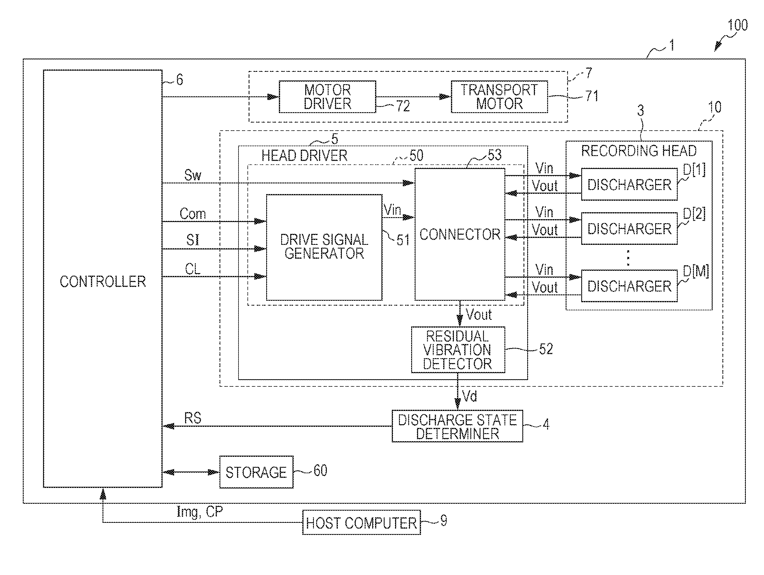
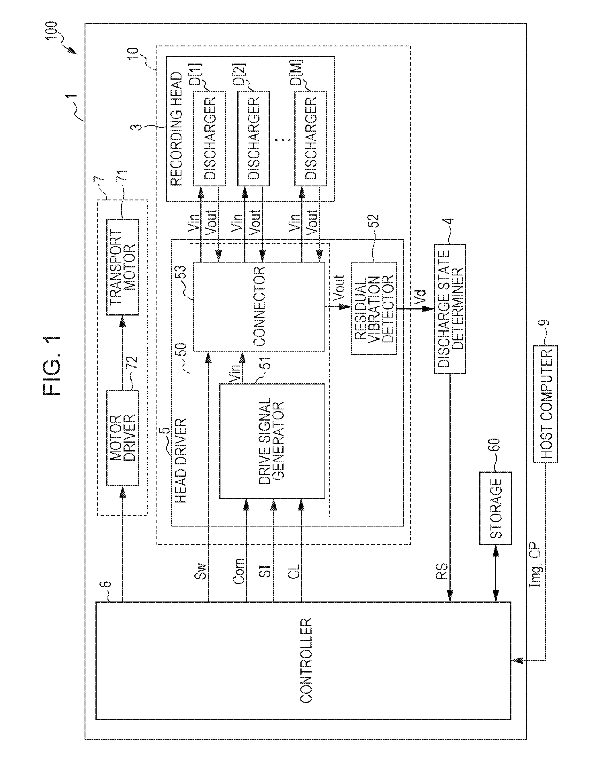
[0054]A configuration of an ink jet printer 1 according to the present embodiment will be described with reference to FIG. 1 and FIG. 2.

[0055]FIG. 1 is a functional block diagram illustrating a configuration of a printing system 100 that includes the ink jet printer 1. The printing system 100 includes the ink jet printer 1 and a host computer 9 such as a personal computer or a digital camera.

[0056]The host computer 9 outputs print data Img and copy number information CP. The print data Img represents an image to be formed by the ink jet printer 1, and the copy number information CP indicates a printed copy number Wcp that is the number of printed copies of the image to be formed by the ink jet printer 1. The ink jet printer 1 perf...

modification example

B. Modification Example

[0234]Various modifications may be carried out to the embodiment described above. Specific forms of modification will be described below. Two or more forms that are arbitrarily selected from the description below may be appropriately combined to the extent not inconsistent with each other.

[0235]Elements of the modification examples described below having an effect or a function equivalent to the embodiment will be designated by the reference sign that is referenced in the above description, and a detailed description of each thereof will be appropriately omitted.

modification example 1

[0236]Supply of the drive signal Vin[m] to the discharger D[m] is stopped during the unit period Tu preceding the one unit period Tu in the above embodiment to maintain the voltage applied to the piezoelectric element 300 at a constant level when the discharger D[m] is the target of the discharge state determination process in the one unit period Tu. However, the invention is not limited to such a form. The voltage applied to the piezoelectric element 300 may be maintained at a constant level by supplying the drive signal Vin[m] having a constant potential level to the discharger D[m]. For example, the drive signal Vin[m] of which the potential is set to the reference potential V0 may be supplied to the discharger D[m] to maintain the voltage applied to the piezoelectric element 300 at a constant level.


PUM


Abstract

Provided is a liquid discharging apparatus including a waveform signal generator that generates a drive waveform signal which includes a plurality of waveforms including an inspection waveform; a first discharger including a first piezoelectric element that is displaced by being supplied with a first drive signal; a first switch that is capable of switching whether to supply the first drive signal to the first piezoelectric element for each unit period; and a detector that detects residual vibration occurring in the first discharger after the first drive signal including the inspection waveform is supplied to the first piezoelectric element, in which the first switch stops supply of the first drive signal to the first piezoelectric element during a unit period that precedes one unit period when the first drive signal including the inspection waveform is supplied to the first piezoelectric element during the one unit period.

Description

CROSS REFERENCE TO RELATED APPLICATIONS[0001]This application claims priority to Japanese Patent Application No. 2015-061842 filed on Mar. 25, 2015. The entire disclosure of Japanese Patent Application No. 2015-061842 is hereby incorporated herein by reference.BACKGROUND[0002]1. Technical Field[0003]The present invention relates to a liquid discharging apparatus, a head unit, a control method for a liquid discharging apparatus, and a control program for a liquid discharging apparatus.[0004]2. Related Art[0005]A liquid discharging apparatus such as an ink jet printer forms an image on a recording medium by driving a discharger disposed in a head unit with a drive signal to discharge liquid such as ink filling a cavity (pressure chamber) of the discharger. In such a liquid discharging apparatus, there may occur an abnormal discharge that is a situation where liquid cannot be normally discharged from the discharger because of thickening of liquid, mingling of an air bubble with liquid ...

Claims


Application Information

Patent Timeline
Patent Type & Authority Applications(United States)
IPC IPC(8): B41J2/045
CPCB41J2/04581B41J2/04588B41J2/0451B41J2/04541B41J2/04593B41J2/04596B41J2002/14354
Inventor KAMIYANAGI, MASASHI
Owner SEIKO EPSON CORP
Why Eureka
Try Eureka